28119 Parallax Inc, 28119 Datasheet - Page 22
28119
Manufacturer Part Number
28119
Description
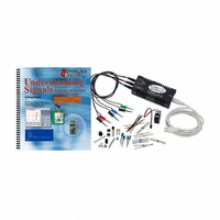
KIT UNDERSTANDING SIGNALS
Manufacturer
Parallax Inc
Datasheet
1.28119.pdf
(137 pages)
Specifications of 28119
Lead Free Status
Contains lead
Accessory Type
Oscilloscope
Interface Type
USB
For Use With/related Products
BASIC Stamp® 2 and Board of Education
Lead Free Status / Rohs Status
Lead free / RoHS Compliant
Available stocks
Company
Part Number
Manufacturer
Quantity
Price
Company:

Part Number:
281197-2
Manufacturer:
TE
Quantity:
20 000
Company:
Part Number:
281197-2
Manufacturer:
MOLEX
Quantity:
2 500


All activities in this text assume that you are using a fresh 9 V battery as your power
supply. Please be aware that using worn-out batteries or alternative power supplies may
alter your voltage signals somewhat from those shown in the book.
For detailed instructions on setting up your BASIC Stamp hardware and software, see
What’s a Microcontroller? under the Further Investigation section at the end of this
chapter.
The Board of Education, BASIC Stamp and HomeWork Board are sold separately. For a
complete list of system and equipment requirements, see Appendix A.
ACTIVITY #1: VIEWING HIGH AND LOW SIGNALS
In this activity we will verify the proper operation of your OPTAscope by viewing simple
high and low signals from the BASIC Stamp.
Parts Required
(1) OPTAscope CH1 probe and ground cable
(2) Jumper wires
Building the High and Low Signals Circuit
This circuit is built the same way for the Board of Education and the BASIC Stamp
HomeWork Board.
√
√
√
√
Plug the probe cable into the CH1 jack on the OPTAscope.
Build the simple circuit shown in Figure 1-14 and Figure 1-15.
Connect the OPTAscope CH1 probe to I/O Pin 14 of your BASIC Stamp.
Connect the black probe to the BASIC Stamp’s Vss connection (ground).
Which probe is which?
controls and signals graphics in the software. Connect the blue-tipped probe cable to the
CH1 jack on the OPTAscope, and the red one to the CH2 jack. The green-tipped cable
plugs into the External Trigger TTL jack. In the wiring diagrams, the probes are labeled for
clarity. The active channel probes are colored (CH1 is blue, CH2 is red); the Ground probes
are black.
The OPTAscope probes are color-coded to correspond with
Related parts for 28119
Image
Part Number
Description
Manufacturer
Datasheet
Request
R


Part Number:
Description:
Microcontroller Modules & Accessories DISCONTINUED BY PARALLAX
Manufacturer:
Parallax Inc

Part Number:
Description:
BOOK UNDERSTANDING SIGNALS
Manufacturer:
Parallax Inc
Datasheet:


Part Number:
Description:
COMPETITION RING FOR SUMOBOT
Manufacturer:
Parallax Inc
Datasheet:


Part Number:
Description:
TEXT INFRARED REMOTE FOR BOE-BOT
Manufacturer:
Parallax Inc
Datasheet:
Part Number:
Description:
BOARD EXPERIMENT+LCD NX-1000
Manufacturer:
Parallax Inc
Datasheet:

Part Number:
Description:
CONTROLLER 16SERVO MOTOR CONTROL
Manufacturer:
Parallax Inc
Datasheet:

Part Number:
Description:
BASIC STAMP LOGIC ANALYZER
Manufacturer:
Parallax Inc
Datasheet:

Part Number:
Description:
IC MCU 2K FLASH 50MHZ SO-18
Manufacturer:
Parallax Inc
Datasheet: