LSN2-T/10-D12N-C Murata Power Solutions Inc, LSN2-T/10-D12N-C Datasheet - Page 8
LSN2-T/10-D12N-C
Manufacturer Part Number
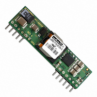
LSN2-T/10-D12N-C
Description
CONV DC/DC 50W 10A 0.75-5V SIP
Manufacturer
Murata Power Solutions Inc
Series
LSN2r
Type
Point of Load (POL) Non-Isolatedr
Datasheet
1.LSN2-T10-W3N-C.pdf
(15 pages)
Specifications of LSN2-T/10-D12N-C
Number Of Outputs
1
Output
0.75 ~ 5V
Power (watts)
50W
Mounting Type
Through Hole
Voltage - Input
8.3 ~ 14V
Package / Case
12-SIP Module
1st Output
0.75 ~ 5 VDC @ 10A
Size / Dimension
2.00" L x 0.32" W x 0.50" H (50.8mm x 8.1mm x 12.7mm)
Power (watts) - Rated
50W
Operating Temperature
-40°C ~ 85°C
Efficiency
95%
Approvals
CSA, EN, UL
Output Power
50 W
Input Voltage Range
8.3 V to 14 V
Input Voltage (nominal)
12 V
Output Voltage (channel 1)
0.75 V to 5 V
Output Current (channel 1)
10 A
Package / Case Size
SIP
Output Type
Low Voltage Selectable
Output Voltage
0.75 V to 5 V
Product
Non-Isolated / POL
Lead Free Status / RoHS Status
Lead free / RoHS Compliant
3rd Output
-
2nd Output
-
Lead Free Status / Rohs Status
Lead free / RoHS Compliant
Other names
811-1801
Available stocks
Company
Part Number
Manufacturer
Quantity
Price

Part Number:
LSN2-T/10-D12N-C
Manufacturer:
MURATA/村田
Quantity:
20 000


whose heat is generated primarily by I
developed using thermocouples to monitor the inductor temperature and
varying the load to keep that temperature below +110°C under the assorted
conditions of air fl ow and air temperature. Once the temperature exceeds
+115°C (approx.), the thermal protection will disable the converter. Automatic
restart occurs after the temperature has dropped below +110°C.
curves on the following pages, LSN2 SIPs maintain virtually constant effi cien-
cy from half to full load, and consequently deliver very impressive temperature
performance even if operating at full load.
subject to numerous factors and tolerances not taken into account here. If you
are attempting to extract the most current out of these units under demand-
ing temperature conditions, we advise you to monitor the output-inductor
temperature to ensure it remains below +110°C at all times.
Start Up Considerations
When power is fi rst applied to the DC/DC converter, operation is different than
when the converter is running and stabilized. There is some risk of start up
diffi culties if you do not observe several application features. Lower output
voltage converters may have more problems here since they tend to have
higher output currents. Operation is most critical with any combination of the
following external factors:
start up surge current may instantaneously reduce the voltage at the input
terminals to below the specifi ed minimum voltage. Even if this voltage depres-
sion is very brief, this may interfere with the on-board controller and possibly
cause a failed start. Or the converter may start but the input current load will
now drive the input voltage below its running low limit and the converter will
shut down.
the voltage may appear to be adequate. Limited external capacitance and/or
too high a source impedance may cause a short downward spike at power up,
causing an instantaneous voltage drop. Use an oscilloscope not a DVM to observe
this spike. The converter’s soft-start controller is sensitive to input voltage. What
matters here is the actual voltage at the input terminals at all times.
lation or brief start up then overcurrent shutdown. Since the input voltage is
The highest temperatures in LSN2 SIPs occur at their output inductor,
As you may deduce from the derating curves and observe in the effi ciency
Lastly, when LSN2 SIPs are installed in system boards, they are obviously
If the input voltage is already at the low limit before power is applied, the
If you measure the input voltage before start up with a Digital Voltmeter (DVM),
Symptoms of start-up diffi culties may include failed started, output oscil-
1 – Low initial input line voltage and/or poor regulation of the input source.
2 – Full output load current on lower output voltage converters.
3 – Slow slew rate of input voltage.
4 – Longer distance to input voltage source and/or higher external input
5 – Limited or insuffi cient ground plane. External wiring that is too small.
6 – Too small external input capacitance. Too high ESR.
7 – High output capacitance causing a start up charge overcurrent surge.
8 – Output loads with excessive inductive reactance or constant current
source impedance.
characteristics.
2
R losses. The derating curves were
www.murata-ps.com
never absolutely constant, the converter may start up at some times and not
at others.
Solutions
To improve start up, review the conditions above. One of the better solutions
is to place a moderate size capacitor very close to the input terminals. You
may need two parallel capacitors. A larger electrolytic or tantalum cap sup-
plies the surge current and a smaller parallel low-ESR ceramic cap gives low
AC impedance. Too large an electrolytic capacitor may have higher internal
impedance (ESR) and/or lower the start up slew rate enough to upset the DC/
DC’s controller. Make sure the capacitors can tolerate refl ected switching cur-
rent pulses from the converter.
converter which starts successfully at 3.3 Volts will turn off if the input voltage
decays to below the input voltage theshold, regardless of external capacitance.
spike. Also, make sure that the input voltage ramps up in a reasonably short
time (less than a few milliseconds). If possible, move the input source closer
to the converter to reduce ohmic losses in the input wiring. Remember that
the input current is carried both by the wiring and the ground plane return.
Make sure the ground plane uses adequate thickness copper. Run additional
bus wire if necessary.
no more) to reduce output noise at the load and to avoid marginal thresh-
old noise problems with external logic. An output cap will also “decouple”
inductive reactance in the load. Certain kinds of electronic loads include
“constant current” characteristics which destabilize the output with insuf-
fi cient capacitance. If the wiring to the eventual load is long, consider placing
this decoupling cap at the load. Use the Remote Sense input to avoid ohmic
voltage drop errors.
the Remote On/Off control fi rst in the off setting (for those converters with an
On/Off Control). After the specifi ed start-up delay (usually under 20 mSec),
turn on the converter. The controller will have already been stabilized. The
short delay will not be noticed in most applications. Be aware of applications
which need “power management” (phased start up).
fi delity. How low is the resistance of your ground plane? What is the inductance
(and distributed capacitance) of external wiring? Even a detailed mathematical
model may not get all aspects of your circuit. Therefore it is diffi cult to give cap
values which serve all applications. Some experimentation may be required.
Pre-Biased Startup
Newer systems with multiple power voltages have an additional problem
besides startup sequencing. Some sections have power already partially ap-
plied (possibly because of earlier power sequencing) or have leakage power
present so that the DC/DC converter must power up into an existing voltage.
This power may either be stored in an external bypass capacitor or supplied
by an active source.
mable logic or because of blocking diode leakage or small currents passed
The capacitors will not help if the input source has poor regulation. A
Increase the input start up voltage if possible to raise the downward voltage
Any added output capacitor should use just enough capacitance (and
An elegant solution to start up problems is to apply the input voltage with
Finally, it is challenging to model some application circuits with absolute
This “pre-biased” condition can also occur with some types of program-
Selectable-Output DC/DC Converters
25 Jun 2010
Non-isolated, DOSA-SIP, 6/10/16A
LSN2 Series
email: sales@murata-ps.com
MDC_LSN2.B07Δ
Page 8 of 15
Related parts for LSN2-T/10-D12N-C
Image
Part Number
Description
Manufacturer
Datasheet
Request
R

Part Number:
Description:
CONV DC/DC 33W 10A .75-3.3V SIP
Manufacturer:
Murata Power Solutions Inc
Datasheet:

Part Number:
Description:
CONV DC/DC 33W 10A .75-3.3V SIP
Manufacturer:
Murata Power Solutions Inc
Datasheet:

Part Number:
Description:
CONV DC/DC 50W 10A 0.75-5V SIP
Manufacturer:
Murata Power Solutions Inc
Datasheet:

Part Number:
Description:
DC/DC Converter
Manufacturer:
Murata Power Solutions Inc
Datasheet:
Part Number:
Description:
DC/DC Converter
Manufacturer:
Murata Power Solutions Inc
Datasheet:
Part Number:
Description:
DC/DC Converter
Manufacturer:
Murata Power Solutions Inc
Datasheet:
Part Number:
Description:
DC/DC Converter
Manufacturer:
Murata Power Solutions Inc
Datasheet:

Part Number:
Description:
DC/DC Converters & Regulators 12Vin 0.8-5Vout 30A 150W Power Good Out
Manufacturer:
Murata Power Solutions Inc
Datasheet:

Part Number:
Description:
DC/DC Converters & Regulators 12Vin 0.8-5Vout 22A 112W NonIso DOSA-SIP
Manufacturer:
Murata Power Solutions Inc
Datasheet:
Part Number:
Description:
DC/DC Converters & Regulators 12Vin 0.8-5Vout 22A 112W Neg polarity
Manufacturer:
Murata Power Solutions Inc
Datasheet:

Part Number:
Description:
Transformers 5Vin 5Vout 200mA 4000Vdc 1:1.33 turn
Manufacturer:
Murata Power Solutions Inc
Datasheet:

Part Number:
Description:
POWER SUPPLY
Manufacturer:
Murata Power Solutions Inc
Datasheet:

Part Number:
Description:
DPM LED MINI 2VDC 3.5DIG LP RED
Manufacturer:
Murata Power Solutions Inc
Datasheet:

Part Number:
Description:
CONV DC/DC 1W 5VIN 5VOUT SIP SGL
Manufacturer:
Murata Power Solutions Inc
Datasheet:

Part Number:
Description:
CONV DC/DC 1W 5VIN 3.3V SIP SGL
Manufacturer:
Murata Power Solutions Inc
Datasheet: