LSM2-T/6-W3N-C Murata Power Solutions Inc, LSM2-T/6-W3N-C Datasheet - Page 5
LSM2-T/6-W3N-C
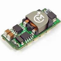
Manufacturer Part Number
LSM2-T/6-W3N-C
Description
CONV DC/DC 19.8W 6A 5V SMD
Manufacturer
Murata Power Solutions Inc
Series
LSM2r
Type
Point of Load (POL) Non-Isolatedr
Datasheet
1.LSM2-T6-W3N-C.pdf
(17 pages)
Specifications of LSM2-T/6-W3N-C
Output
0.75 ~ 3.3V
Number Of Outputs
1
Power (watts)
19W
Mounting Type
Surface Mount
Voltage - Input
2.4 ~ 5.5V
Package / Case
8-DIP SMD Module
1st Output
0.75 ~ 3.3 VDC @ 6A
Size / Dimension
1.30" L x 0.53" W x 0.34" H (33mm x 13.5mm x 8.6mm)
Power (watts) - Rated
19.8W
Operating Temperature
-40°C ~ 85°C
Efficiency
95.5%
Approvals
CSA, cUL, EN, UL
Dc / Dc Converter O/p Type
Variable
No. Of Outputs
1
Input Voltage
2.4V To 5.5V
Power Rating
19.8W
Output Voltage
5V
Output Current
6A
Approval Bodies
UL, CSA
Supply Voltage
5V
Product
Non-Isolated / POL
Output Power
20 W
Input Voltage Range
2.4 V to 5.5 V
Output Voltage (channel 1)
0.75 V to 3.3 V
Output Current (channel 1)
6 A
Lead Free Status / RoHS Status
Lead free / RoHS Compliant
3rd Output
-
2nd Output
-
Lead Free Status / Rohs Status
Lead free / RoHS Compliant
Other names
811-1782-2
Available stocks
Company
Part Number
Manufacturer
Quantity
Price

Part Number:
LSM2-T/6-W3N-C
Manufacturer:
MURATA/村田
Quantity:
20 000


Start-Up Time
The V
ing input voltage crosses the lower limit of the specifi ed input voltage range
and the fully loaded output voltage enters and remains within its specifi ed
accuracy band. Actual measured times will vary with input source impedance,
external input capacitance, and the slew rate and fi nal value of the input volt-
age as it appears to the converter.
On/Off Control with the nominal input voltage already applied to the converter.
The specifi cation defi nes the interval between the time at which the converter
is turned on and the fully loaded output voltage enters and remains within its
specifi ed accuracy band. See Typical Performance Curves.
Remote Sense
LSM2 Series offer an output sense function. The sense function enables
point-of-use regulation for overcoming moderate IR drops in conductors and/or
cabling. Since these are non-isolated devices whose inputs and outputs usually
share the same ground plane, sense is provided only for the +Output.
The On/Off to V
IN
to V
OUT
+OUTPUT
COMMON
+SENSE
Start-Up Time is the interval between the time at which a ramp-
Figure 3. Measuring Output Ripple/Noise (PARD)
OUT
Figure 2. Measuring Input Ripple Current
Start-Up Time assumes the converter is turned off via the
C1 = NA
C2 = 22μF TANTALUM
LOAD 2-3 INCHES (51-76mm) FROM MODULE
6
4
3
C1
COPPER STRIP
COPPER STRIP
C2
SCOPE
www.murata-ps.com
R
LOAD
the DC/DC converter’s output. The sense line carries very little current and
consequently requires a minimal cross-sectional-area conductor. As such,
it is not a low-impedance point and must be treated with care in layout and
cabling. Sense lines should be run adjacent to signals (preferably ground), and
in cable and/or discrete-wiring applications, twisted-pair or similar techniques
should be used. To prevent high frequency voltage differences between V
and Sense, we recommend installation of a 1000pF capacitor close to the
converter.
the +Output and +Sense pins that do not exceed 10% of V
rent and voltage at the converter’s output pins. Use of trim and sense functions
can cause the output voltage to increase, thereby increasing output power
beyond the LSM2's specifi ed rating. Therefore:
serves to protect the sense function by limiting the output current fl owing
through the sense line if the main output is disconnected. It also prevents
output voltage runaway if the sense connection is disconnected.
be tied to +Output at the DC/DC converter pins.
Sense Input
Use the Sense input with caution. Many applications do not need the Sense
connection. Sense is intended to correct small output accuracy errors caused
by the resistive ohmic drop in output wiring as output current increases. This
output drop (the difference between Sense and V
converter) should not be allowed to exceed 0.5V. Consider using heavier wire if
this drop is excessive.
careful where it is connected. Any long, distributed wiring and/or signifi cant
inductance introduced into the Sense control loop can adversely affect overall
system stability. If in doubt, test the application, and observe the DC/DC's output
transient response during step loads. There should be no appreciable ringing or
oscillation. You may also adjust the output trim slightly to compensate for voltage
loss in any external fi lter elements. Do not exceed maximum power ratings.
On/Off Control
The On/Off Control pin may be used for remote on/off operation. LSM2 Series
DC/DC converters are designed so that they are enabled when the control pin
is left open (open collector).
chanical relay or open-collector/open-drain drive circuit (optically isolated if
appropriate). The drive circuit should be able to sink appropriate current when
activated and withstand appropriate voltage when deactivated.
The remote sense line is part of the feedback control loop regulating
The sense function is capable of compensating for voltage drops between
Power derating (output current limiting) is based upon maximum output cur-
The internal 10.5: resistor between +Sense and +Output (see Figure 1)
Note: If the sense function is not used for remote regulation, +Sense must
Sense is connected at the load and corrects for resistive errors only. Be
Dynamic control of the on/off function is best accomplished with a me-
[V
(V
OUT
OUT
(+) – Common] – [Sense(+) – Common] d 10%V
at pins) x (I
Selectable-Output POL DC/DC Converters
OUT
) d rated output power
25 Jun 2010
Single Output, Non-Isolated
MDC_LSM2
LSM2 Series
OUT
email: sales@murata-ps.com
when measured at the
Series.B09Δ
OUT
OUT
.
Page 5 of 17
OUT
Related parts for LSM2-T/6-W3N-C
Image
Part Number
Description
Manufacturer
Datasheet
Request
R

Part Number:
Description:
CONV DC/DC 30W 6A 12V SMD
Manufacturer:
Murata Power Solutions Inc
Datasheet:
Part Number:
Description:
CONV DC/DC 19.8W 6A 5V SMD
Manufacturer:
Murata Power Solutions Inc
Datasheet:
Part Number:
Description:
CONV DC/DC 30W 6A 12V SMD
Manufacturer:
Murata Power Solutions Inc
Datasheet:

Part Number:
Description:
DC/DC Converter
Manufacturer:
Murata Power Solutions Inc
Datasheet:
Part Number:
Description:
DC/DC Converter
Manufacturer:
Murata Power Solutions Inc
Datasheet:
Part Number:
Description:
DC/DC Converter
Manufacturer:
Murata Power Solutions Inc
Datasheet:
Part Number:
Description:
DC/DC Converter
Manufacturer:
Murata Power Solutions Inc
Datasheet:

Part Number:
Description:
CONV DC/DC 125W 30A 12V SMD
Manufacturer:
Murata Power Solutions Inc
Datasheet:
Part Number:
Description:
CONV DC/DC 125W 30A 12V SMD
Manufacturer:
Murata Power Solutions Inc
Datasheet:
Part Number:
Description:
CONV DC/DC 33W 10A 5V SMD
Manufacturer:
Murata Power Solutions Inc
Datasheet:

Part Number:
Description:
DC/DC Converter
Manufacturer:
Murata Power Solutions Inc
Datasheet:

Part Number:
Description:
Transformers 5Vin 5Vout 200mA 4000Vdc 1:1.33 turn
Manufacturer:
Murata Power Solutions Inc
Datasheet:

Part Number:
Description:
POWER SUPPLY
Manufacturer:
Murata Power Solutions Inc
Datasheet:

Part Number:
Description:
DPM LED MINI 2VDC 3.5DIG LP RED
Manufacturer:
Murata Power Solutions Inc
Datasheet:

Part Number:
Description:
CONV DC/DC 1W 5VIN 5VOUT SIP SGL
Manufacturer:
Murata Power Solutions Inc
Datasheet: