HYS72T128000HR-3S-B Qimonda, HYS72T128000HR-3S-B Datasheet - Page 26
HYS72T128000HR-3S-B
Manufacturer Part Number
HYS72T128000HR-3S-B
Description
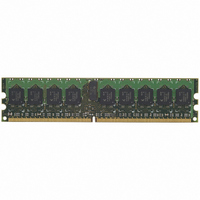
MODULE DDR2 1GB 240-DIMM
Manufacturer
Qimonda
Datasheet
1.HYS72T128000HR-3S-B.pdf
(52 pages)
Specifications of HYS72T128000HR-3S-B
Memory Type
DDR2 SDRAM
Memory Size
1GB
Speed
333MHz
Package / Case
240-DIMM
Lead Free Status / RoHS Status
Lead free / RoHS Compliant
Other names
675-1028


3.3.3
This chapter describes the ODT AC electrical characteristics.
1) New units, '
2) ODT turn on time min is when the device leaves high impedance and ODT resistance begins to turn on. ODT turn on time max is when the
3) ODT turn off time min. is when the device starts to turn off ODT resistance. ODT turn off time max is when the bus is in high impedance.
1) ODT turn on time min. is when the device leaves high impedance and ODT resistance begins to turn on. ODT turn on time max is when
Rev. 1.2, 2007-01
03292006-JXZQ-CG6T
Symbol
t
t
t
t
t
t
t
t
Symbol
t
t
t
t
t
t
t
t
AOND
AON
AONPD
AOFD
AOF
AOFPD
ANPD
AXPD
AOND
AON
AONPD
AOFD
AOF
AOFPD
ANPD
AXPD
under operation. Unit 'nCK' represents one clock cycle of the input clock, counting the actual clock edges. Note that in DDR2-400 and
DDR2-533, '
be registered at Tm + 2, even if (Tm + 2 - Tm) is 2 ×
ODT resistance is fully on. Both are measured from
cycles after the clock edge that registered a first ODT HIGH counting the actual input clock edges.
Both are measured from
3 ns is assumed,
LOW and by counting the actual input clock edge.
the ODT resistance is fully on. Both are measured from
10 ns (= 2 x 5 ns) after the clock edge that registered a first ODT HIGH if
Parameter / Condition
ODT turn-on delay
ODT turn-on
ODT turn-on (Power-Down Modes)
ODT turn-off delay
ODT turn-off
ODT turn-off (Power-Down Modes)
ODT to Power Down Mode Entry Latency
ODT Power Down Exit Latency
Parameter / Condition
ODT turn-on delay
ODT turn-on
ODT turn-on (Power-Down Modes)
ODT turn-off delay
ODT turn-off
ODT turn-off (Power-Down Modes)
ODT to Power Down Mode Entry Latency
ODT Power Down Exit Latency
t
t
CK.AVG
CK
' is used for both concepts. Example:
t
' and 'nCK', are introduced in DDR2-667 and DDR2-800. Unit '
AOFD
ODT AC Electrical Characteristics
= 1.5 ns (0.5 × 3 ns) after the second trailing clock edge counting from the clock edge that registered a first ODT
t
AOFD
. Both are measured from
ODT AC Characteristics and Operating Conditions for DDR2-533 & DDR2-400
t
AOND
t
XP
t
CK.AVG
t
= 2 [nCK] means; if Power Down exit is registered at Tm, an Active command may
ODT AC Character. and Operating Conditions for DDR2-667
AOFD
t
, which is interpreted differently per speed bin. For DDR2-667/800,
AOND
+
, which is interpreted differently per speed bin. For DDR2-667/800, if
, which is interpreted differently per speed bin. For DDR2-400/533,
t
EPR.2PER(MIN)
Values
Min.
2
t
t
2.5
t
t
3
8
Values
Min.
2
t
t
2.5
t
t
3
8
AC.MIN
AC.MIN
AC.MIN
AC.MIN
AC.MIN
AC.MIN
AC.MIN
AC.MIN
26
+ 2 ns
+ 2 ns
+ 2 ns
+ 2 ns
.
t
CK
= 5 ns.
t
CK.AVG
Max.
2
t
2
t
2.5
—
—
Max.
2
t
2
t
2.5
—
2.5
2.5
—
AC.MAX
AC.MAX
AC.MAX
AC.MAX
HYS72T[64/128/256]xxxHR–[3S/3.7/5]–B
t
t
CK +
CK +
' represents the actual
t
t
CK +
CK +
t
t
+ 0.7 ns
AC.MAX
+ 0.6 ns
+ 1 ns
AC.MAX
+ 0.6 ns
t
t
240-Pin Registered DDR2 SDRAM
AC.MAX
AC.MAX
+ 1 ns
+ 1 ns
+ 1 ns
+ 1 ns
t
CK.AVG
Internet Data Sheet
Unit
nCK
ns
ns
nCK
ns
ns
nCK
nCK
Unit
t
ns
ns
t
ns
ns
t
t
CK
CK
CK
CK
TABLE 16
of the input clock
TABLE 17
t
AOND
Note
Note
1)
1)2)
1)
1)
1)3)
1)
1)
1)
—
1)
—
—
2)
—
—
—
is 2 clock
t
CK.AVG
t
AOND
is
=
Related parts for HYS72T128000HR-3S-B
Image
Part Number
Description
Manufacturer
Datasheet
Request
R

Part Number:
Description:
BGA
Manufacturer:
Qimonda
Datasheet:
Part Number:
Description:
BGA
Manufacturer:
Qimonda
Datasheet:
Part Number:
Description:
Manufacturer:
Qimonda
Datasheet:
Part Number:
Description:
Manufacturer:
Qimonda
Datasheet:
Part Number:
Description:
DDR2 16Mx16, 667MHz, FBGA84, leadfree
Manufacturer:
Qimonda
Datasheet:
Part Number:
Description:
DDR2 32Mx16, 533MHz, FBGA84, leadfree
Manufacturer:
Qimonda
Datasheet:

Part Number:
Description:
HYB18TC1G160BF-3.71-Gbit DDR2 SDRAM
Manufacturer:
QIMONDA Qimonda AG
Datasheet:
Part Number:
Description:
HYB18TC1G800BF-3S1-Gbit DDR2 SDRAM
Manufacturer:
QIMONDA Qimonda AG
Datasheet: