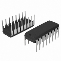
NCP1395APG ON Semiconductor, NCP1395APG Datasheet - Page 21

NCP1395APG
Manufacturer Part Number
NCP1395APG
Description
IC CTRLR PWM OVP 16DIP
Manufacturer
ON Semiconductor
Datasheet
1.NCP1395APG.pdf
(27 pages)
Specifications of NCP1395APG
Pwm Type
Voltage Mode
Number Of Outputs
1
Frequency - Max
1MHz
Duty Cycle
52%
Voltage - Supply
10.3 V ~ 20 V
Buck
No
Boost
No
Flyback
No
Inverting
No
Doubler
No
Divider
No
Cuk
No
Isolated
No
Operating Temperature
-40°C ~ 125°C
Package / Case
16-DIP (0.300", 7.62mm)
Frequency-max
1MHz
Switching Frequency
50 KHz to 1 MHz
Mounting Style
Through Hole
Duty Cycle (max)
52 %
Input Voltage
11V
Frequency
1MHz
Supply Voltage Range
20V
Digital Ic Case Style
DIP
No. Of Pins
16
Operating Temperature Range
-40°C To +125°C
Svhc
No SVHC (15-Dec-2010)
Base Number
1395
Rohs Compliant
Yes
Lead Free Status / RoHS Status
Lead free / RoHS Compliant
(A and B pulse), the IBO source is activated and creates
a hysteresis. The hysteresis level actually depends
on the circuit: NCP1395A features a 28 mA whereas
the NCP1395B uses a 83 mA current. Changes are
IBO is off
IBO is on
into Equation 2, then solve for Rupper:
350 V, and turn it off for Vbulk2 equals 250 V, then we
obtain:
IBO = 28 mA
Rupper = 3.6 MW
Rlower = 10 kW
45 mW when the front−end PFC stage delivers 400 V.
measurement as long as the NTC and the optocoupler are
not activated. As soon as the secondary optocoupler senses
To the contrary, when the internal BO signal is high
We can now extract Rlower from Equation 1 and plug it
If we decide to turn on our converter for Vbulk1 equals
The bridge power dissipation is 400
In Figure 47, Q1 is blocked and does not bother the BO
Rlower + VBO
Rupper + Rlower
Figure 47. Adding a comparator on the BO pin offers a way to latch−off the controller.
Vout
IBO
V()) + Vbulk2
Vbulk1−Vbulk2
Vbulk1−VBO
(Vbulk1−VBO)
VBO
NTC
V
CC
Q1
V()) + Vbulk1
2
/3.601 MW =
Rlower ) Rupper
Vbulk
http://onsemi.com
Rlower
Rupper
Rlower
BO
21
Rlower ) Rupper
implemented to a) reduce the standby power on the
NCP1395A b) improve the noise immunity on the
NCP1395B. Knowing these values, it becomes possible to
select the turn−on and turn−off levels via a few lines of
algebra:
IBO = 83 mA
Rupper = 1.2 MW
Rlower = 3.4 kW
front−end PFC stage delivers 400 V. Figure 46 simulation
result confirms our calculations.
Latch−Off Protection
fully turned off and stay latched. This can happen in
presence of an overvoltage (the feedback loop is drifting)
or when an overtemperature is detected. Due to the addition
of a comparator on the BO pin, a simple external circuit can
lift up this pin above VLATCH (5.0 V typical) and
permanently disable pulses. The V
down below 5.0 V typically to reset the controller.
an OVP condition, or the NTC reacts to a high ambient
temperature, Q1 base is brought to ground and the BO pin
goes up, permanently latching off the controller.
) IBO
The bridge power dissipation is 132 mW when the
There are some situations where the converter shall be
Rlower
+
VBO
+
Vlatch
+
−
Rlower
Rlower ) Rupper
IBO
+
−
20 ms
RC
Rupper
To permanent
latch
Vdd
CC
BO
needs to be cycled
(eq. 1)
(eq. 2)


