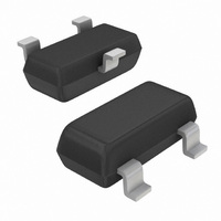
TLV431ASN1T1G ON Semiconductor, TLV431ASN1T1G Datasheet - Page 6

TLV431ASN1T1G
Manufacturer Part Number
TLV431ASN1T1G
Description
IC REG SHUNT ADJ 1.24V SOT23
Manufacturer
ON Semiconductor
Datasheet
1.TLV431ALPG.pdf
(14 pages)
Specifications of TLV431ASN1T1G
Reference Type
Shunt, Adjustable
Voltage - Output
1.24 ~ 16 V
Tolerance
±1%
Number Of Channels
1
Current - Cathode
55µA
Current - Output
20mA
Operating Temperature
-40°C ~ 85°C
Mounting Type
Surface Mount
Package / Case
SOT-23-3, TO-236-3, Micro3™, SSD3, SST3
Product
Voltage References
Topology
Shunt References
Output Voltage
Adjustable
Initial Accuracy
1 %
Series Vref - Input Voltage (max)
18 V
Shunt Current (max)
20 mA
Maximum Operating Temperature
+ 85 C
Minimum Operating Temperature
- 40 C
Mounting Style
SMD/SMT
Shunt Current (min)
0.08 mA
Fixed / Adjust / Prog
Adjust
Output Voltage (max)
1.24 to 16V
Reference Voltage Accuracy (max)
1
Input Voltage (max)
18V
Operating Temp Range
-40C to 85C
Operating Temperature Classification
Industrial
Mounting
Surface Mount
Pin Count
3
Package Type
SOT-23
Lead Free Status / RoHS Status
Lead free / RoHS Compliant
Voltage - Input
-
Temperature Coefficient
-
Current - Quiescent
-
Lead Free Status / Rohs Status
Lead free / RoHS Compliant
Other names
TLV431ASN1T1GOS
TLV431ASN1T1GOS
TLV431ASN1T1GOSTR
TLV431ASN1T1GOS
TLV431ASN1T1GOSTR
Available stocks
Company
Part Number
Manufacturer
Quantity
Price
Part Number:
TLV431ASN1T1G
Manufacturer:
ON/安森美
Quantity:
20 000
Stability
circuit configurations for the worst case conditions with the
load capacitance mounted as close as possible to the device.
The required load capacitance for stable operation can vary
depending on the operating temperature and capacitor
Figures 18 and 19 show the stability boundaries and
350
325
300
275
250
5.0
25
20
15
10
0
pF
10
10
Stable
Figure 18. Stability Boundary Conditions
100
pF
Figure 16. Spectral Noise Density
B
100
1.0
nF
C
A
L
, LOAD CAPACITANCE
f, FREQUENCY (Hz)
0.01
mF
Stable
T
1.0 k
A
= 25 C
0.1
mF
Input
V
I
T
K
A
KA
= 10 mA
= 25 C
= V
I
1.0
mF
ref
ref
10 k
C
D
I
10
mF
K
http://onsemi.com
Stable
Output
100 k
100
mF
6
equivalent series resistance (ESR). Ceramic or tantalum
surface mount capacitors are recommended for both
temperature and ESR. The application circuit stability
should be verified over the anticipated operating current and
temperature ranges.
1.5
1.0
0.5
2.0
0
0
0
Input
1.0
V+
Figure 19. Test Circuit for Figure 18
Unstable
Regions
T
A
A, C
B, D
2.0
= 25 C
1.8 k
50
Figure 17. Pulse Response
1.0 k
W
3.0
Output
R1
R2
4.0
t, TIME (ms)
V
V
(V)
5.0
KA
ref
5.0
6.0
(kW)
Output
30.4
R1
Input
0
I
7.0
K
(kW)
8.0
R2
10
C
L
9.0
10.0


