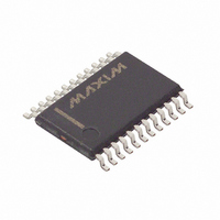
DS1780E Maxim Integrated Products, DS1780E Datasheet - Page 18

DS1780E
Manufacturer Part Number
DS1780E
Description
IC CPU PERIPHERAL MON 24-TSSOP
Manufacturer
Maxim Integrated Products
Datasheet
1.DS1780E.pdf
(28 pages)
Specifications of DS1780E
Function
Thermal Monitor, CPU Peripherals
Topology
ADC (Sigma Delta), Comparator, Fan Speed Control, Register Bank
Sensor Type
Internal
Sensing Temperature
-40°C ~ 125°C
Output Type
I²C™/SMBus™
Output Alarm
No
Output Fan
Yes
Voltage - Supply
2.8 V ~ 5.75 V
Operating Temperature
-40°C ~ 125°C
Mounting Type
Surface Mount
Package / Case
24-TSSOP
Full Temp Accuracy
+/- 12 %
Digital Output - Bus Interface
Serial (2-Wire)
Digital Output - Number Of Bits
8 bit
Maximum Operating Temperature
+ 125 C
Minimum Operating Temperature
- 40 C
Lead Free Status / RoHS Status
Contains lead / RoHS non-compliant
Available stocks
Company
Part Number
Manufacturer
Quantity
Price
Company:
Part Number:
DS1780E
Manufacturer:
MAX
Quantity:
3 000
Part Number:
DS1780E
Manufacturer:
DALLAS
Quantity:
20 000
Part Number:
DS1780E+T&R
Manufacturer:
MAXIM/美信
Quantity:
20 000
Company:
Part Number:
DS1780E+TR
Manufacturer:
MAXIM
Quantity:
1 001
Company:
Part Number:
DS1780E-TR
Manufacturer:
ICS
Quantity:
933
Company:
Part Number:
DS1780E/TR
Manufacturer:
XILINX
Quantity:
17
INTERRUPT INT STATUS REGISTER 2 (ADDRESS 0X42; POWER-UP
DEFAULT=00h) Table 10.4
Note: Anytime the
automatically reset to power-up state (except CHS, which can only be cleared by CHS reset). In the case
of the VOLTAGE priority indication, if two or more voltages were out of LIMITS, then another
indication would automatically be generated if it were not handled during the ISR.
The errant voltage may be masked until the operator has time to clear the errant condition or set the limit
higher/lower.
INT MASK REGISTER 1 (ADDRESS 0X43; POWER-UP DEFAULT=00h)
Table 10.5
INT MASK REGISTER 2 (ADDRESS 0X44; POWER-UP DEFAULT=00h)
Table 10.6
BIT
BIT
BIT
0
1
2
3
4
5
6
7
0
1
2
3
4
5
6
7
0
1
2
3
4
5
6
7
Chassis_Error
Reset Enable
+12V_Error
V
-12V/V
Intrusion)
Reserved
Reserved
Reserved
CHS_sec
Reserved
Reserved
Reserved
Reserved
Reserved
Reserved
Reserved
CCP2
(Chassis
NAME
NAME
NAME
+V
+2.5V
+3.3V
FAN1
FAN2
Temp
+12V
-12V/
+5V
_Error
CCP1
CCP2
INT
R/W
R/W
R/W
R/W
R/W
R/W
R/W
R/W
R/W
R/W
R/W
R/W
R/W
R/W
R/W
R/W
R/W
R/W
R/W
R
R
R
R
R
R
R
R
Status Registers are read out, the conditions (i.e., Registers) that are read are
A 1 indicates a High or Low limit has been exceeded.
A 1 indicates a High or Low limit has been exceeded.
0
0
A 1 indicates Chassis Intrusion has gone high.
0
0
0
A 1 disables the corresponding interrupt status bit for
A 1 disables the corresponding interrupt status bit for
A 1 disables the corresponding interrupt status bit for
A 1 disables the corresponding interrupt status bit for
A 1 disables the corresponding interrupt status bit for
Power on default = 0.
A 1 disables the corresponding interrupt status bit for
A 1 disables the corresponding interrupt status bit for
A 1 disables the corresponding interrupt status bit for
A 1 disables the corresponding interrupt status bit for
Power-up Default = 0.
Power-up Default = 0.
A 1 disables the corresponding interrupt status bit for
Power-up Default = 0.
Power-up Default = 0.
A 1 enables the RESET in the configuration register.
18 of 28
DESCRIPTION
DESCRIPTION
DESCRIPTION
INT
INT
INT
INT
INT
INT
INT
INT
INT
INT
interrupt.
interrupt.
interrupt.
interrupt.
interrupt.
interrupt.
interrupt.
interrupt.
interrupt.
interrupt.


