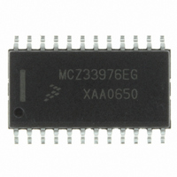
MCZ33976EG Freescale Semiconductor, MCZ33976EG Datasheet - Page 25

MCZ33976EG
Manufacturer Part Number
MCZ33976EG
Description
IC DRIVER DUAL GAUGE SPI 24-SOIC
Manufacturer
Freescale Semiconductor
Type
Serial Peripheral Interface (SPI) Dual Step Motor Gauge Driverr
Datasheet
1.MCZ33976EG.pdf
(41 pages)
Specifications of MCZ33976EG
Applications
Stepper Motor Driver, 2 Phase
Number Of Outputs
2
Current - Output
100mA
Voltage - Supply
6.5 V ~ 26 V
Operating Temperature
-40°C ~ 125°C
Mounting Type
Surface Mount
Package / Case
24-SOIC (7.5mm Width)
Supply Current
4 mA
Maximum Operating Temperature
+ 125 C
Mounting Style
SMD/SMT
Minimum Operating Temperature
- 40 C
Lead Free Status / RoHS Status
Lead free / RoHS Compliant
Voltage - Load
-
Lead Free Status / Rohs Status
Lead free / RoHS Compliant
Available stocks
Company
Part Number
Manufacturer
Quantity
Price
Part Number:
MCZ33976EG
Manufacturer:
FREESCALE
Quantity:
20 000
Table 28. Gauge 0 and 1 Pointer Velocity Status Output Register
The bits in
table value that indicates the actual velocity step location
(refer to
time that the
ramp is truncated with the RMPSELR, the velocity position
step that will be read when the pointer is no longer moving will
STATE MACHINE OPERATION
velocities and acceleration and deceleration.The purpose of
the step motor state machine is to drive the motor with
maximum performance while remaining within the motor’s
voltage, velocity, and acceleration constraints.
deceleration phase begins at the correct time and pointer
position. When commanded, the motor will accelerate
constantly to the maximum velocity, then move toward the
commanded position. Eventually, the pointer will reach the
calculated location where the movement has to decelerate,
slowing safely to a stop at the desired position. During the
Analog Integrated Circuit Device Data
Freescale Semiconductor
Read
Write
Bits
1V7:1V0 (OD15:OD8) — These 8 bits represent the step
Note For both sets of bits,1V7:1V0 and 0V7:0V0, if the
The two-phase step motor has maximum allowable
A requirement of the state machine is to ensure the
OD15
Table
1V7
Table 28
–
CS
30, page 28) of the Gauge 1 pointer at the
OD14
transitions to a logic [0].
1V6
–
are read-only bits.
OD13
1V5
–
OD12
1V4
–
OD11
1V3
–
OD10
1V2
–
OD9
1V1
–
OD8
1V0
–
be the velocity position that identifies it in the untruncated
ramp (e.g., if RS = 2, then the velocity step location will be 3
when the pointer is at the commanded position).
table value that indicates the actual velocity step location
(refer to
CS
deceleration phase, the motor will not exceed the maximum
deceleration.
microstepped with 24 steps per electrical revolution (see
Figure
degrees of pointer movement. There is a second (smaller)
state machine in the IC controlling these microsteps. This
state machine receives clockwise or counter-clockwise index
commands at intervals, stepping the motor in the appropriate
direction by adjusting the current in each coil. Normalized
values are provided in
OD7
0V7
0V7:0V0 (OD7:OD0) — These 8 bits represent the step
During normal operation, both step motor rotors are
transitions to a logic [0].
–
9). A complete electrical revolution results in two
Table
OD6
0V6
–
30) of the Gauge 0 pointer at the time that the
OD5
0V5
–
Table
LOGIC COMMANDS AND REGISTERS
OD4
0V4
–
FUNCTIONAL DEVICE OPERATION
29, page 26.
OD3
0V3
–
OD21
0V2
–
OD1
0V1
–
OD0
0V0
33976
–
25


