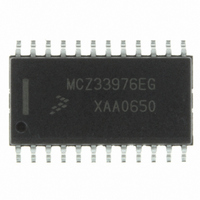
MCZ33976EG Freescale Semiconductor, MCZ33976EG Datasheet - Page 21

MCZ33976EG
Manufacturer Part Number
MCZ33976EG
Description
IC DRIVER DUAL GAUGE SPI 24-SOIC
Manufacturer
Freescale Semiconductor
Type
Serial Peripheral Interface (SPI) Dual Step Motor Gauge Driverr
Datasheet
1.MCZ33976EG.pdf
(41 pages)
Specifications of MCZ33976EG
Applications
Stepper Motor Driver, 2 Phase
Number Of Outputs
2
Current - Output
100mA
Voltage - Supply
6.5 V ~ 26 V
Operating Temperature
-40°C ~ 125°C
Mounting Type
Surface Mount
Package / Case
24-SOIC (7.5mm Width)
Supply Current
4 mA
Maximum Operating Temperature
+ 125 C
Mounting Style
SMD/SMT
Minimum Operating Temperature
- 40 C
Lead Free Status / RoHS Status
Lead free / RoHS Compliant
Voltage - Load
-
Lead Free Status / Rohs Status
Lead free / RoHS Compliant
Available stocks
Company
Part Number
Manufacturer
Quantity
Price
Part Number:
MCZ33976EG
Manufacturer:
FREESCALE
Quantity:
20 000
Table 18. Truncated Velocity Steps
SO Communication
as configured with the PECCR command bits PE11:PE8, is
loaded into the output register and the data is clocked out
MSB (OD15) first. Following a
determines if the shifted-in message was of a valid length (a
valid message length is one that is greater than 0 bits and a
multiple of 16 bits) and, if so, latches the incoming data into
the appropriate registers.
is now able to accept new status information. Fault status
information will be latched and held until the Device Status
Table 20. Device Status Output Register
The bits in
pointer is moving.
Analog Integrated Circuit Device Data
Freescale Semiconductor
Read
Write
Bits
When the
At this time, the SO pin is tri-stated and the status register
DIR1 (OD15) — This bit indicates the direction Gauge 1
• 0 = Toward position 0
• 1 = Away from position 0
RS3
0
0
0
0
0
0
0
0
1
1
1
1
1
1
1
1
OD15
DIR1
Table 20
–
CS
RS2
0
0
0
0
1
1
1
1
0
0
0
0
1
1
1
1
OD14
DIR0 0POS1 0POS0 CMD1 CMD0
pin is pulled low, the internal status register,
–
are read-only bits.
OD13
RS1
0
0
1
1
0
0
1
1
0
0
1
1
0
0
1
1
–
CS
OD12
–
RS0
transition 0 to 1, the device
0
1
0
1
0
1
0
1
0
1
0
1
0
1
0
1
OD11
–
Position # (RS)
Zero Velocity
OD10
–
10
11
12
13
14
15
0
1
2
3
4
5
6
7
8
9
OD9
OV
–
OD8
UV
–
Output register is selected and it is clocked out via the SO. If
the message length was determined to be invalid, the fault
information will not be cleared and will be transmitted again
during the next valid SPI message. Pointer status information
bits (e.g., pointer position, velocity, and commanded position
status) will always reflect the real time state of the pointer.
representative of the initial message bits clocked into the SI
pin since the
feature is useful for daisy-chaining devices as well as
message verification.
of the PECCR command determines the nature of the status
data that is clocked out of the SO pin.
available:
until either the PECCR command bits PE11:PE8 (D11:D8)
are written to select another or the device is reset. Each of the
Status types and the PECCR bit necessary to select them are
described in the following paragraphs.
Device Status Information
Device Status output:
Table 19.
pointer is moving.
x = Don’t care.
OD7
CAL
1. Device Status (refer to
2. RTZ Accumulator Status (refer to
3. Gauge 0 Pointer Position Status (refer to
4. Gauge 1 Pointer Position Status (refer to
5. Gauge 1 and 2 Pointer Velocity Status (refer to
Any bits clocked out of the SO pin after the first 16 are
As described above, the last valid write to bits PE11:PE8
There are five different types of status information
Once a specific status type is selected, it will not change
Most recent valid PECCR command resulting in the
DIR0 (OD14) — This bit indicates the direction Gauge 0
• 0 = Toward position 0
• 1 = Away from position 0
–
page 24)
page 24)
Table
D11
0
OVUV MOV1 MOV0
OD6
–
28, page 24)
CS
pin first transitioned to a logic [0]. This
OD5
–
D10
x
LOGIC COMMANDS AND REGISTERS
OD4
–
FUNCTIONAL DEVICE OPERATION
Table
RTZ1
OD3
–
20, page 21)
D9
x
Table
RTZ0
OD2
–
22, page 23)
Table
Table
OD1
OT1
–
D8
x
24,
26,
OD0
OT0
33976
–
21


