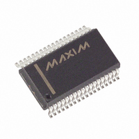
MAX5952AEAX+ Maxim Integrated Products, MAX5952AEAX+ Datasheet - Page 31

MAX5952AEAX+
Manufacturer Part Number
MAX5952AEAX+
Description
IC PSE CNTRLR FOR POE 36-SSOP
Manufacturer
Maxim Integrated Products
Type
Power Over Ethernet Controller (PoE)r
Datasheet
1.MAX5952AUAX.pdf
(50 pages)
Specifications of MAX5952AEAX+
Applications
Remote Peripherals (Industrial Controls, Cameras, Data Access)
Internal Switch(s)
No
Operating Temperature
-40°C ~ 85°C
Mounting Type
Surface Mount
Package / Case
36-BSOP (0.300", 7.5mm Width)
Product
Controllers & Switches
Supply Voltage (max)
5.5 V
Supply Voltage (min)
1.71 V
Power Dissipation
941 mW
Operating Temperature Range
- 40 C to + 85 C
Mounting Style
SMD/SMT
Supply Current
4.8 mA
Input Voltage
60V
Digital Ic Case Style
SSOP
No. Of Pins
36
Uvlo
28.5V
Frequency
400kHz
Interface
I2C
Termination Type
SMD
Rohs Compliant
Yes
Filter Terminals
SMD
Controller Type
Power Over Ethernet PD
Lead Free Status / RoHS Status
Lead free / RoHS Compliant
PGOOD_ is set to 1 (Table 14) at the end of the power-
up startup period if the power-good condition is met (0
< (V
must remain valid for more than t
PGOOD_. PGOOD_ is reset to 0 whenever the output
falls out of the power-good condition. A fault condition
immediately forces PGOOD_ low.
A3, A2, A1, A0 (Table 15) represent the four LSBs of
the MAX5952 address (Table 4). During a reset, the
device latches into R11h. These four bits address from
Table 14. Power Status Register
Table 15. Address Input Status Register
PGOOD4
PGOOD3
PGOOD2
PGOOD1
PWR_EN4
PWR_EN3
PWR_EN2
PWR_EN1
Reserved
Reserved
A3
A2
A1
A0
MIDSPAN
AUTO
OUT
SYMBOL
SYMBOL
- V
EE
ADDRESS = 10h
ADDRESS = 11h
) < PG
______________________________________________________________________________________
TH
). The power-good condition
BIT
BIT
7
6
5
4
3
2
1
0
7
6
5
4
3
2
1
0
High-Power, Quad, PSE Controller
PGOOD
R/W
R/W
R
R
R
R
R
R
R
R
R
R
R
R
R
R
R
R
to assert
Power-good condition on port 4
Power-good condition on port 3
Power-good condition on port 2
Power-good condition on port 1
Power is enabled on port 4
Power is enabled on port 3
Power is enabled on port 2
Power is enabled on port 1
Reserved
Reserved
Device address, A3 pin latched-in status
Device address, A2 pin latched-in status
Device address, A1 pin latched-in status
Device address, A0 pin latched-in status
MIDSPAN input’s latched-in status
AUTO input’s latched-in status
for Power-Over-Ethernet
PWR_EN_ is set to 1 when the port power is turned on.
PWR_EN resets to 0 as soon as the port turns off. Any
transition of PGOOD_ and PWR_EN_ bits set the corre-
sponding bit in the power event registers R02h/R03h
(Table 8). A reset sets R10h = 00h.
the corresponding inputs as well as the state of the
MIDSPAN and AUTO inputs. Changes to those inputs
during normal operation are ignored.
DESCRIPTION
DESCRIPTION
31


