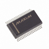
MAX5952AEAX+ Maxim Integrated Products, MAX5952AEAX+ Datasheet - Page 26

MAX5952AEAX+
Manufacturer Part Number
MAX5952AEAX+
Description
IC PSE CNTRLR FOR POE 36-SSOP
Manufacturer
Maxim Integrated Products
Type
Power Over Ethernet Controller (PoE)r
Datasheet
1.MAX5952AUAX.pdf
(50 pages)
Specifications of MAX5952AEAX+
Applications
Remote Peripherals (Industrial Controls, Cameras, Data Access)
Internal Switch(s)
No
Operating Temperature
-40°C ~ 85°C
Mounting Type
Surface Mount
Package / Case
36-BSOP (0.300", 7.5mm Width)
Product
Controllers & Switches
Supply Voltage (max)
5.5 V
Supply Voltage (min)
1.71 V
Power Dissipation
941 mW
Operating Temperature Range
- 40 C to + 85 C
Mounting Style
SMD/SMT
Supply Current
4.8 mA
Input Voltage
60V
Digital Ic Case Style
SSOP
No. Of Pins
36
Uvlo
28.5V
Frequency
400kHz
Interface
I2C
Termination Type
SMD
Rohs Compliant
Yes
Filter Terminals
SMD
Controller Type
Power Over Ethernet PD
Lead Free Status / RoHS Status
Lead free / RoHS Compliant
High-Power, Quad, PSE Controller
for Power-Over-Ethernet
The interrupt register (Table 6) summarizes the event
register status and is used to send an interrupt signal
(INT goes low) to the controller. Writing a 1 to R1Ah[7]
clears all interrupt and events registers. A reset sets
R00h to 00h.
Table 6. Interrupt Register
Table 7. Interrupt Mask Register
26
MASK7
MASK6
MASK5
MASK4
MASK3
MASK2
MASK1
MASK0
SUP_FLT
TSTR_FLT
IMAX_FLT
CL_END
DET_END
LD_DISC
PG_INT
PE_INT
SYMBOL
SYMBOL
______________________________________________________________________________________
Register Map and Description
ADDRESS = 01h
ADDRESS = 00h
BIT
BIT
7
6
5
4
3
2
1
0
7
6
5
4
3
2
1
0
R/W
R/W
R/W
R/W
R/W
R/W
R/W
R/W
R/W
R/W
R
R
R
R
R
R
R
R
Interrupt mask bit 7. A logic-high enables the SUP_FLT interrupts. A logic-low disables the
SUP_FLT interrupts.
Interrupt mask bit 6. A logic-high enables the TSTR_FLT interrupts. A logic-low disables
the TSTR_FLT interrupts.
Interrupt mask bit 5. A logic-high enables the IMAX_FLT interrupts. A logic-low disables
the IMAX_FLT interrupts.
Interrupt mask bit 4. A logic-high enables the CL_END interrupts. A logic-low disables the
CL_END interrupts.
Interrupt mask bit 3. A logic-high enables the DET_END interrupts. A logic-low disables the
DET_END interrupts.
Interrupt mask bit 2. A logic-high enables the LD_DISC interrupts. A logic-low disables the
LD_DISC interrupts.
Interrupt mask bit 1. A logic-high enables the PG_INT interrupts. A logic-low disables the
PG_INT interrupts.
Interrupt mask bit 0. A logic-high enables the PEN_INT interrupts. A logic-low disables the
PEN_INT interrupts.
Interrupt signal for supply faults. SUP_FLT is the logic OR of all the bits [7:0] in register
R0Ah/R0Bh (Table 12).
Interrupt signal for startup failures. TSTR_FLT is the logic OR of bits [7:0] in register
R08h/R09h (Table 11).
Interrupt signal for current-limit violations. IMAX_FLT is the logic OR of bits [3:0] in register
R06h/R07h (Table 10).
Interrupt signal for completion of classification. CL_END is the logic OR of bits [7:4] in
register R04h/R05h (Table 9).
Interrupt signal for completion of detection. DET_END is the logic OR of bits [3:0] in
register R04h/R05h (Table 9).
Interrupt signal for load disconnection. LD_DISC is the logic OR of bits [7:4] in register
R06h/R07h (Table 10).
Interrupt signal for PGOOD status change. PG_INT is the logic OR of bits [7:4] in register
R02h/R03h (Table 8).
Interrupt signal for power-enable status change. PEN_INT is the logic OR of bits [3:0] in
register R02h/R03h (Table 8).
INT_EN (R17h[7]) is a global interrupt mask (Table 7).
The MASK_ bits activate the corresponding interrupt
bits in register R00h. Writing a 0 to INT_EN (R17h[7])
disables the INT output.
A reset sets R01h to AAA00A00b where A is the state
of the AUTO input prior to the reset.
DESCRIPTION
DESCRIPTION


