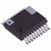
ADE7760ARSRL Analog Devices Inc, ADE7760ARSRL Datasheet - Page 20

ADE7760ARSRL
Manufacturer Part Number
ADE7760ARSRL
Description
IC ENERGY METER W/OCFD 20SSOP TR
Manufacturer
Analog Devices Inc
Datasheet
1.ADE7760ARS.pdf
(24 pages)
Specifications of ADE7760ARSRL
Rohs Status
RoHS non-compliant
Input Impedance
400 KOhm
Measurement Error
0.1%
Voltage - I/o High
2.4V
Voltage - I/o Low
0.8V
Current - Supply
4mA
Voltage - Supply
4.75 V ~ 5.25 V
Operating Temperature
-40°C ~ 85°C
Mounting Type
Surface Mount
Package / Case
20-SSOP (0.200", 5.30mm Width)
Meter Type
Single Phase
Lead Free Status / Rohs Status
Not Compliant
ADE7760
Table 9. F1 and F2 Frequency with Half-Scale AC Inputs
S0
0
0
1
1
When selecting a suitable F
frequency output at I
of 100 impulses /kWh should be compared with Column 4 of
Table 9. The frequency that is closest in Table 9 determines the
best choice of frequency (F
maximum current of 40 A is being designed, the output
frequency on F1 and F2 with a meter constant of
100 impulses /kWh is 0.266 Hz at 40 A and 240 V (from
Table 8). Looking at Table 9, the closest frequency to 0.266 Hz
in Column 4 is 0.17 Hz. Therefore, F2 (3.4 Hz; see Table 5) is
selected for this design.
Frequency Outputs
Figure 2 shows a timing diagram for the various frequency
outputs. The high frequency CF output is intended to be used
for communications and calibration purposes. CF produces a
90 ms wide, active high pulse (t
tional to active power. The CF output frequencies are given in
Table 7. As in the case of F1 and F2, if the period of CF (t
below 180 ms, the CF pulse width is set to half the period. For
example, if the CF frequency is 20 Hz, the CF pulse width is
25 ms.
S1
0
1
0
1
F
1.72
3.44
6.86
13.5
1-4
MAX
(maximum load) with a meter constant
Frequency on F1 and F2,
CH1 and CH2,
Half-Scale AC Inputs
0.085 Hz
0.17 Hz
0.34 Hz
0.68 Hz
1–4
1–4
). For example, if a meter with a
frequency for a meter design, the
4
) at a frequency that is propor-
5
) falls
Rev. 0 | Page 20 of 24
No-Load Threshold
The ADE7760 also includes a no-load threshold and startup
current feature that eliminates any creep effects in the
meter. The ADE7760 is designed to issue a minimum output
frequency. Any load generating a frequency lower than this
minimum frequency does not cause a pulse to be issued on F1,
F2, or CF. The minimum output frequency is given as 0.0045%
of the full-scale output frequency. (See Table 7 for maximum
output frequencies for ac signals.)
For example, an energy meter with a meter constant of
100 impulses /kWh on F1, F2 using SCF = 1, S1 = 0, and S0 = 1,
the maximum output frequency at F1 or F2 would be 0.68 Hz
and 43.52 Hz on CF. The minimum output frequency at F1 or
F2 would be 0.0045% of 0.68 Hz or 3.06 × 10
be 1.96 × 10
load threshold would be equivalent to 1.1 W of load or a startup
current of 4.6 mA at 240 V. Compare this value to the IEC61036
specification, which states that the meter must start up with a
load equal to or less than 0.4% I
is equivalent to 20 mA.
Note that the no-load threshold is not enabled when using the
high CF frequency mode: SCF = 0, S1 = S0 = 1.
NEGATIVE POWER INFORMATION
The ADE7760 detects when the current and voltage channels
have a phase shift greater than 90 ° . This mechanism can detect
wrong connection of the meter or generation of negative power.
The REVP pin output goes active high when negative power is
detected and active low, when positive power is detected. The
REVP pin output changes state as a pulse is issued on CF.
–3
Hz at CF (64 × F1 Hz). In this example, the no-
B
. For a 5 A (I
–5
B
) meter, 0.4% of I
Hz. This would
B


