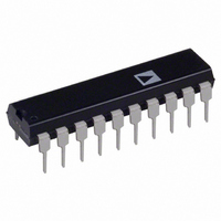
ADE7756AN Analog Devices Inc, ADE7756AN Datasheet - Page 24

ADE7756AN
Manufacturer Part Number
ADE7756AN
Description
IC ENERGY METERING 20-DIP
Manufacturer
Analog Devices Inc
Datasheet
1.ADE7756AN.pdf
(32 pages)
Specifications of ADE7756AN
Rohs Status
RoHS non-compliant
Input Impedance
390 KOhm
Measurement Error
0.1%
Voltage - I/o High
2.4V
Voltage - I/o Low
0.8V
Current - Supply
3mA
Voltage - Supply
4.75 V ~ 5.25 V
Operating Temperature
-40°C ~ 85°C
Mounting Type
Through Hole
Package / Case
20-DIP (0.300", 7.62mm)
Meter Type
Single Phase
Lead Free Status / RoHS Status
Not Compliant
ADE7756
reduce the ripple. Also, averaging the output frequency by using
a longer gate time for the counter will achieve the same results.
ENERGY CALIBRATION
By using the on-chip zero-crossing detection on Channel 2 the
energy calibration can be greatly simplified and the time required
to calibrate the meter can be significantly reduced. To use the
zero-cross detection the ADE7756 is placed in calibration mode
by setting Bit 7 (CMODE) in the Mode register. In Calibration
Mode the ADE7756 accumulates the Active Power signal in the
Active Energy register for an integral number of half cycles, as
shown in Figure 34. The number of half-line cycles is specified
in the SAGCYC register. The ADE7756 can accumulate Active
Power for up to 255 half-cycles. Because the Active Power is
integrated on an integral number of line cycles, the sinusoidal
component is reduced to zero. This eliminates any ripple in the
energy calculation. Energy is calculated more accurately and in
a shorter time because integration period can be shortened. At
the end of an energy calibration cycle the SAG flag in the Inter-
rupt Status register is set; this will cause the SAG output to go
active low. If the SAG enable bit in the Interrupt Enable register
is enabled, the IRQ output will also go active low. Thus the IRQ
line can be used to signal the end of a calibration also. Another
calibration cycle will start as long as the CMODE bit in the
Mode register is set. Note that the result of the first calibration
is invalid and must be ignored. The result of all subsequent
calibration cycles is correct.
From Equations 5 and 11,
where n is an integer and T is the line cycle period.
Since the sinusoidal component is integrated over an integer
number of line cycles, its value is always zero.
Therefore:
E t
E t
E t
( )
( ) = ∫
( ) =
nT
∫
0
VIdt
VInt
E(t)
nT
0
VIdt
–
1 2
+
4
fl
VI
/ .
8 9
f
l
(1 + 2
t
Hz
VI
∫
VIt
f
nT
l
0
/8.9Hz
cos (
2
SIN(4
ω
t dt
)
f
l
t)
(13)
(14)
(15)
CALIBRATING THE ENERGY METER
Calculating the Average Active Power
When calibrating the ADE7756, the first step is to calibrate
the frequency on CF to some required meter constant, e.g.,
3200 imp/kWh.
In order to determine the output frequency on CF, the average
value of the Active Power signal (output of LPF2) must first be
determined. One convenient way to do this is to use the calibra-
tion mode. When the CMODE (Bit 7) bit in the Mode register
is set to a Logic 1, energy is accumulated over an integer num-
ber of half-line cycles as described in the last section.
Since the line frequency is fixed at, say, 60 Hz, and the number
of half-cycles of integration is specified, the total integration
time is given as:
For 255 half-cycles this would give a total integration time of
2.125 seconds. This would mean the energy register was updated
2.125/1.1175 µs (4/CLKIN) times. The average output value of
LPF2 is given as:
Or equivalently, in terms of contents of various ADE7756 regis-
ters and CLKIN and line frequencies (fl):
where fl is the line frequency.
Calibrating the Frequency at CF
Once the average Active Power signal is calculated it can be used
to determine the frequency at CF before calibration. When the
frequency before calibration is known, the Calibration Frequency
Divider register (CFDIV) and the Active Power Gain register
(APGAIN) can be adjusted to produce the required frequency
on CF. In this example, a meter constant of 3200 imp/kWh is
chosen as an appropriate constant. This means that under a
steady load of 1 kW, the output frequency on CF would be,
MULTIPLIER
CHANNEL 2
Average word LPF
Frequency CF
CCCDh
FROM
Number of times AENERGY
ACTIVE POWER
ADC
00h
SIGNAL – P
LPF2
Contents of AENERGY
(
LPF1
2 60
(
×
)
1
=
Hz
3200
11
60
2
23
39
ZERO CROSS
)
=
DETECT
min
×
AENERGY
imp kWh
number of half cycles
SAGCYC
×
WAVEFORM [23:0]
/
60
AENERGY[39:0}
APOS [11:0]
sec
[ : ]
39 0
[ : ]
[ : ]
39 0
7 0
=
CALIBRATION
[ : ]
SAGCYC[7:0]
39 0
3200
3600
CONTROL
at the end
×
was updated
CLKIN
× ×
=
8
0 8888
.
0
0
0
fl
Hz
(16)


