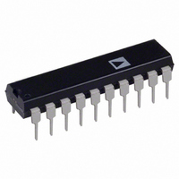
ADE7756AN Analog Devices Inc, ADE7756AN Datasheet - Page 21

ADE7756AN
Manufacturer Part Number
ADE7756AN
Description
IC ENERGY METERING 20-DIP
Manufacturer
Analog Devices Inc
Datasheet
1.ADE7756AN.pdf
(32 pages)
Specifications of ADE7756AN
Rohs Status
RoHS non-compliant
Input Impedance
390 KOhm
Measurement Error
0.1%
Voltage - I/o High
2.4V
Voltage - I/o Low
0.8V
Current - Supply
3mA
Voltage - Supply
4.75 V ~ 5.25 V
Operating Temperature
-40°C ~ 85°C
Mounting Type
Through Hole
Package / Case
20-DIP (0.300", 7.62mm)
Meter Type
Single Phase
Lead Free Status / RoHS Status
Not Compliant
ACTIVE POWER CALCULATION
Electrical power is defined as the rate of energy flow from source to
load. It is given by the product of the voltage and current wave-
forms. The resulting waveform is called the instantaneous power
signal and it is equal to the rate of energy flow at every instant of
time. The unit of power is the watt or joules/sec. Equation 3
gives an expression for the instantaneous power signal in an
ac system.
where
The average power over an integral number of line cycles (n) is
given by the expression in Equation 4.
where
and
Note that the active power is equal to the dc component of the
instantaneous power signal p(t) in Equation 3 , i.e., VI. This is
the relationship used to calculate active power in the ADE7756.
The instantaneous power signal p(t) is generated by multiplying
the current and voltage signals. The dc component of the instan-
taneous power signal is then extracted by LPF2 (Low-Pass Filter)
to obtain the active power information. This process is graphi-
cally illustrated in Figure 26. Since LPF2 does not have an ideal
“brick wall” frequency response—see Figure 27—the Active
Power signal will have some ripple due to the instantaneous
power signal. This ripple is sinusoidal and has a frequency equal
to twice the line frequency. Since the ripple is sinusoidal in
nature it will be removed when the Active Power signal is inte-
grated to calculate Energy—see Energy Calculation section.
V = rms voltage,
T is the line cycle period.
P is referred to as the Active or Real Power.
I = rms current.
v t
i t
P
p t
p t
( )
( )
( )
( )
=
CCCDh
1999Ah
00000h
= 2
= 2
=
=
nT
V. I.
1
VI VI
v t
( )
nT
∫
0
INSTANTANEOUS
POWER SIGNAL
V
I
–
VOLTAGE
V(t) =
CURRENT
I(t) =
×
p t dt VI
sin(
( )
sin(
i t
( )
cos (
2
2
ω
ω
t
=
t
)
I
V
)
2 ω
SIN( t)
SIN( t)
t
p(t) = V
)
1 – V
1
ACTIVE REAL POWER
SIGNAL = V
COS(2 t)
I
(1)
(2)
(3)
(4)
Figure 28 shows the signal processing chain for the Active
Power calculation in the ADE7756. As explained, the Active
Power is calculated by low-pass filtering the instantaneous
power signal.
Shown in Figure 29 is the maximum code (Hexadecimal) out-
put range for the Active Power signal (LPF2). Note that the
output range changes, depending on the contents of the Active
Power Gain register—see Channel 1 ADC section. The mini-
mum output range is given when the Active Power Gain register
contents are equal to 800h, and the maximum range is given
by writing 7FFh to the Active Power Gain register. This can
be used to calibrate the Active Power (or Energy) calculation
in the ADE7756.
V
I
–12
–16
–20
–24
CURRENT SIGNAL – I(t)
VOLTAGE SIGNAL – V(t)
–4
–8
1999Ah
F999Ah
CCCDh
E6666h
0
00000h
F3333h
6666h
1
HPF
CHANNEL 1 (ACTIVE POWER)
CALIBRATION RANGE
1
MULTIPLIER
000h
20
APGAIN[11:0]
3
7FFh
FREQUENCY – Hz
INSTANTANEOUS POWER SIGNAL
p(t) = –40%FS TO +40%FS
1999Ah
20
800h
00h
10
LPF2
CCCDh
+30% FS
+20% FS
+10% FS
–10% FS
–20% FS
–30% FS
ACTIVE POWER
SIGNAL – P
ADE7756
30
POSITIVE
POWER
NEGATIVE
POWER
100


