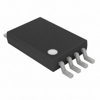
DS2756E+ Maxim Integrated Products, DS2756E+ Datasheet - Page 3

DS2756E+
Manufacturer Part Number
DS2756E+
Description
IC FUEL GAUGE BATT 8TSSOP
Manufacturer
Maxim Integrated Products
Datasheet
1.DS2756E.pdf
(27 pages)
Specifications of DS2756E+
Function
Fuel, Gas Gauge/Monitor
Battery Type
Lithium-Ion (Li-Ion), Lithium-Polymer (Li-Pol)
Voltage - Supply
3 V ~ 5.5 V
Operating Temperature
-40°C ~ 85°C
Mounting Type
Surface Mount
Package / Case
8-TSSOP
Operating Supply Voltage
3 V to 5.5 V
Supply Current
75 uA
Maximum Operating Temperature
+ 85 C
Minimum Operating Temperature
- 40 C
Charge Safety Timers
Yes
Mounting Style
SMD/SMT
Temperature Monitoring
Yes
Lead Free Status / RoHS Status
Lead free / RoHS Compliant
ELECTRICAL CHARACTERISTICS—1-WIRE INTERFACE
(3.0V V
EEPROM RELIABILITY SPECIFICATION
(3.0V V
Note 1:
Note 2:
Note 3:
Note 4:
Note 5:
Note 6:
Note 7:
Note 8:
Note 9:
Note 10:
Note 11:
Period
Undervoltage Detect
Undervoltage Delay
Internal Timebase
Accuracy
Snapshot Trigger 0
Snapshot Delay
STANDARD TIMING
Time Slot
Recovery Time
Write-0 Low Time
Write-1 Low Time
Read Data Valid
Reset Time High
Reset Time Low
Presence-Detect High
Presence-Detect Low
Interrupt Time Low
OVERDRIVE TIMING
Time Slot
Recovery Time
Write-0 Low Time
Write-1 Low Time
Read Data Valid
Reset Time High
Reset Time Low
Presence-Detect High
Presence-Detect Low
Interrupt Time Low
Copy to EEPROM Time
EEPROM Copy Endurance
PARAMETER
PARAMETER
DD
DD
All voltages are referenced to V
Specifications relative to V
Summation of worst case time base and current measurement sampling errors.
Continuous offset cancellation corrects offset errors in the current measurement system. Individual values reported by the
Current register have a maximum offset of ±0.5 LSb’s (±7.8125V). Individual values reported in the Average Current register
have a maximum offset of ±2 LSb’s (±7.8125V).
Current Gain Error specifies the gain error in the Current register value compared to a reference voltage between IS1 and IS2.
The DS2756 does not compensate for sense resistor characteristics, and any error terms arising from the sense resistor should
be taken into account when calculating total current measurement error.
Achieving the 24 Hour Accumulated Current Error assumes positive offset accumulation blanking is enabled (OBEN bit set) and
can require a one time 3.5s in-system calibration after mounting to the printed circuit board. Variations in temperature and supply
voltage are compensated for by periodic offset corrections performed automatically during Active mode operation.
Voltage offset measurement is with respect to 4.2V at +25°C.
Self heating due to output pin loading and sense resistor power dissipation can alter the Temperature reading from ambient
conditions.
Typical value for t
Interface timings and t
Four year data retention at +50C.
Measured during the Suspend Timeout. Does not include active period of suspend cycle.
4.5V, T
4.5V, T
ERR
A
A
valid at 3.7V and +25C. t
= -20C to +70C.)
= -20C to +70C.)
SYMBOL
SUS_ERR
SYMBOL
t
t
t
t
t
t
t
t
t
t
t
t
t
t
t
t
t
t
t
t
V
LOW0
LOW1
RSTH
t
LOW0
LOW1
RSTH
t
SDLY
SLOT
RSTL
SLOT
RSTL
UVD
ERR
SWL
REC
RDV
PDH
REC
RDV
PDH
PDL
PDL
IS1
t
t
UV
IL
IL
N
t
EEC
.
- V
EEC
SS
IS2
.
.
2.4V < V
(Note 9)
(Note 10)
CONDITIONS
ERR
DD
CONDITIONS
applies to all internal timings (ex. f
< 4.5V (Note 1)
3 of 27
50,000
2.45
MIN
MIN
480
480
480
79
80
60
60
15
60
48
48
48
1
1
1
6
1
6
1
2
8
SAMP
, t
SLEEP
TYP
TYP
100
2.5
82
1
2
, t
UVD
) except for the 1-Wire
MAX
1920
MAX
2.55
120
120
119
960
240
192
85
2
16
15
15
60
16
16
80
24
10
2
2
6
UNITS
UNITS
cycles
ms
ms
s
s
s
s
s
s
s
s
s
s
s
s
s
s
s
s
s
s
s
s
s
s
%
V


