74LVC1G18GW,125 NXP Semiconductors, 74LVC1G18GW,125 Datasheet
74LVC1G18GW,125
Specifications of 74LVC1G18GW,125
74LVC1G18GW-G
935273781125


Related parts for 74LVC1G18GW,125


74LVC1G18GW,125 Summary of contents
Page 1
Rev. 02 — 30 August 2007 1. General description The 74LVC1G18 is a 1-of-2 non-inverting demultiplexer with a 3-state output. The device buffers the data on input pin A and passes it ...
Page 2
... NXP Semiconductors 4. Marking Table 2. Marking Type number 74LVC1G18GW 74LVC1G18GV 5. Functional diagram Fig 1. Logic symbol 6. Pinning information 6.1 Pinning Fig 2. Pin configuration 6.2 Pin description Table 3. Pin description Symbol S GND 74LVC1G18_2 Product data sheet 1-of-2 non-inverting demultiplexer with 3-state deselected output ...
Page 3
... NXP Semiconductors 7. Functional description [1] Table 4. Function table Input [ HIGH voltage level LOW voltage level high-impedance OFF-state 8. Limiting values Table 5. Limiting values In accordance with the Absolute Maximum Rating System (IEC 60134). Voltages are referenced to GND (ground = 0 V). Symbol Parameter V supply voltage CC I input clamping current ...
Page 4
... NXP Semiconductors 10. Static characteristics Table 7. Static characteristics At recommended operating conditions. Voltages are referenced to GND (ground = 0 V). Symbol Parameter +85 C amb V HIGH-level input voltage IH V LOW-level input voltage IL V HIGH-level output voltage OH V LOW-level output voltage OL I input leakage current I I OFF-state output current ...
Page 5
... NXP Semiconductors Table 7. Static characteristics At recommended operating conditions. Voltages are referenced to GND (ground = 0 V). Symbol Parameter V LOW-level input voltage IL V HIGH-level output voltage OH V LOW-level output voltage OL I input leakage current I I OFF-state output current OZ I power-off leakage current OFF I supply current ...
Page 6
... NXP Semiconductors 11. Dynamic characteristics Table 8. Dynamic characteristics Voltages are referenced to GND (ground = 0 V). For test circuit see Symbol Parameter Conditions t propagation delay A to nY; see enable time S to nY; see disable time S to nY; see dis power dissipation capacitance [1] Typical values are measured at T [2] ...
Page 7
... NXP Semiconductors 12. AC waveforms Measurement points are given in Fig 3. Input A to output Y propagation delays Table 9. Measurement points 1. 1.95 V 0.5 2 2.7 V 0.5 2.7 V 1 3.6 V 1 5.5 V 0.5 S input nY output LOW-to-OFF OFF-to-LOW nY output HIGH-to-OFF OFF-to-HIGH Measurement points are given 0 2.7 V. ...
Page 8
... NXP Semiconductors Test data is given in Table 10. Definitions for test circuit Load resistance Load capacitance including jig and probe capacitance Termination resistance should be equal to the output impedance External voltage for measuring switching times. EXT Fig 5. Load circuitry for switching times Table 10. ...
Page 9
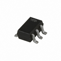
... NXP Semiconductors 13. Package outline Plastic surface-mounted package; 6 leads y 6 pin 1 index DIMENSIONS (mm are the original dimensions UNIT max 0.30 1.1 0.25 mm 0.1 0.20 0.8 0.10 OUTLINE VERSION IEC SOT363 Fig 6. Package outline SOT363 (SC-88) 74LVC1G18_2 Product data sheet 1-of-2 non-inverting demultiplexer with 3-state deselected output ...
Page 10
... NXP Semiconductors Plastic surface-mounted package (TSOP6); 6 leads y 6 pin 1 index 1 e DIMENSIONS (mm are the original dimensions UNIT b p 0.1 0.40 1.1 0.26 mm 0.013 0.25 0.9 0.10 OUTLINE VERSION IEC SOT457 Fig 7. Package outline SOT457 (SC-74) 74LVC1G18_2 Product data sheet 1-of-2 non-inverting demultiplexer with 3-state deselected output ...
Page 11
... Document ID Release date 74LVC1G18_2 20070830 • Modifications: The format of this data sheet has been redesigned to comply with the new identity guidelines of NXP Semiconductors. • Legal texts have been adapted to the new company name where appropriate. • In leakage and supply current. ...
Page 12
... For detailed and full information see the relevant full data sheet, which is available on request via the local NXP Semiconductors sales office. In case of any inconsistency or conflict with the short data sheet, the full data sheet shall prevail ...
Page 13
... NXP Semiconductors 18. Contents 1 General description . . . . . . . . . . . . . . . . . . . . . . 1 2 Features . . . . . . . . . . . . . . . . . . . . . . . . . . . . . . . 1 3 Ordering information . . . . . . . . . . . . . . . . . . . . . 1 4 Marking . . . . . . . . . . . . . . . . . . . . . . . . . . . . . . . . 2 5 Functional diagram . . . . . . . . . . . . . . . . . . . . . . 2 6 Pinning information . . . . . . . . . . . . . . . . . . . . . . 2 6.1 Pinning . . . . . . . . . . . . . . . . . . . . . . . . . . . . . . . 2 6.2 Pin description . . . . . . . . . . . . . . . . . . . . . . . . . 2 7 Functional description . . . . . . . . . . . . . . . . . . . 3 8 Limiting values Recommended operating conditions Static characteristics Dynamic characteristics . . . . . . . . . . . . . . . . . . waveforms . . . . . . . . . . . . . . . . . . . . . . . . . . 7 13 Package outline . . . . . . . . . . . . . . . . . . . . . . . . . 9 14 Abbreviations ...