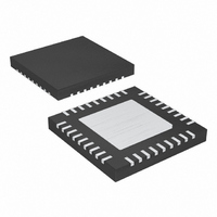
MAX9742ETX+ Maxim Integrated Products, MAX9742ETX+ Datasheet - Page 30

MAX9742ETX+
Manufacturer Part Number
MAX9742ETX+
Description
IC AMP AUDIO PWR 20.5W D 36TQFN
Manufacturer
Maxim Integrated Products
Type
Class Dr
Datasheet
1.MAX9742ETX.pdf
(36 pages)
Specifications of MAX9742ETX+
Output Type
2-Channel (Stereo)
Max Output Power X Channels @ Load
20.5W x 2 @ 8 Ohm
Voltage - Supply
20 V ~ 40 V, ±10 V ~ 20 V
Features
Depop, Differential Inputs, Mute, Short-Circuit and Thermal Protection, Shutdown
Mounting Type
Surface Mount
Package / Case
36-TQFN Exposed Pad
Product
Class-D
Output Power
16 W
Thd Plus Noise
0.08 %
Supply Current
15 mA
Maximum Power Dissipation
2.86 W
Maximum Operating Temperature
+ 85 C
Mounting Style
SMD/SMT
Audio Load Resistance
4 Ohms
Minimum Operating Temperature
- 40 C
Lead Free Status / RoHS Status
Lead free / RoHS Compliant
These copper paths must be as wide as possible. Each
of these paths contributes to the overall thermal capa-
bilities of the system.
The copper polygon to which the exposed paddle is
attached should have multiple vias to the opposite side
of the PCB, where they connect to another copper poly-
gon. Make this polygon as large as possible within the
system’s constraints for signal routing.
Additional improvements are possible if all the traces
from the device are made as wide as possible.
Although the IC pins are not the primary thermal path
out of the package, they do provide a small amount.
The total improvement would not exceed approximately
10%, but it could make the difference between accept-
able performance and thermal problems.
If operating in higher ambient temperatures, it is possi-
ble to improve the thermal performance of a PCB with
the addition of an external heatsink. The thermal resis-
tance to this heatsink must be kept as low as possible
to maximize its performance. With a bottom-side
exposed paddle, the lowest resistance thermal path is
on the bottom of the PCB. The topside of the IC is not a
significant thermal path for the device, and therefore, is
not a cost-effective location for a heatsink. Place the
inductor of the external LC output filter in close proximi-
ty to the IC. This not only helps minimize EMI radiation
at the output traces, but also helps draw heat away
from the MAX9742.
Single-/Dual-Supply, Stereo 16W,
Class D Amplifier with Differential Inputs
30
______________________________________________________________________________________
Auxiliary Heatsinking
PROCESS: BCD
TOP VIEW
BOOTL
OUTL
OUTL
INL+
N.C.
SUB
N.C.
INL-
FBL
1
2
3
4
5
6
7
8
9
(6mm × 6mm × 0.8mm)
+
MAX9742
TQFN
Pin Configuration
Chip Information
27
26
25
24
23
22
21
20
19
N.C.
OUTR
OUTR
BOOTR
REGLS
NSENSE
INR+
INR-
FBR


