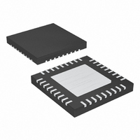
MAX9742ETX+ Maxim Integrated Products, MAX9742ETX+ Datasheet - Page 16

MAX9742ETX+
Manufacturer Part Number
MAX9742ETX+
Description
IC AMP AUDIO PWR 20.5W D 36TQFN
Manufacturer
Maxim Integrated Products
Type
Class Dr
Datasheet
1.MAX9742ETX.pdf
(36 pages)
Specifications of MAX9742ETX+
Output Type
2-Channel (Stereo)
Max Output Power X Channels @ Load
20.5W x 2 @ 8 Ohm
Voltage - Supply
20 V ~ 40 V, ±10 V ~ 20 V
Features
Depop, Differential Inputs, Mute, Short-Circuit and Thermal Protection, Shutdown
Mounting Type
Surface Mount
Package / Case
36-TQFN Exposed Pad
Product
Class-D
Output Power
16 W
Thd Plus Noise
0.08 %
Supply Current
15 mA
Maximum Power Dissipation
2.86 W
Maximum Operating Temperature
+ 85 C
Mounting Style
SMD/SMT
Audio Load Resistance
4 Ohms
Minimum Operating Temperature
- 40 C
Lead Free Status / RoHS Status
Lead free / RoHS Compliant
Single-/Dual-Supply, Stereo 16W,
Class D Amplifier with Differential Inputs
The MAX9742 features a low-power shutdown mode
that reduces quiescent current consumption to less
than 0.5mA in single-supply mode and less than 1µA in
dual-supply mode. Drive SHDN low to place the device
into shutdown mode. Connect SHDN to a logic-high for
normal operation.
The maximum voltage that may be applied to the SHDN
input is 4V (see the Absolute Maximum Ratings sec-
tion). If the SHDN input must be controlled by a 5V
logic signal, limit the maximum voltage that can be
applied to the SHDN input to 4V through an external
resistive divider.
The MAX9742 features comprehensive click-and-pop
suppression that minimizes audible transients on start-
up and shutdown. While in shutdown, the half-bridge
output transistor switches are turned off, causing each
output to go high impedance. During startup, or power-
up, the input amplifiers are muted and an internal loop
sets the modulator bias voltages to the correct levels,
minimizing audible clicks and pops when the output
half-bridge is enabled. The value of the soft-start
capacitor, C
and startup time of the MAX9742 (see the Soft-Start
Capacitor (C
suppression when powering up an audio system, drive
SHDN or SFT (see the Mute Function section) to 0V
until the rest of the circuitry in the system has had
enough time to stabilize. This ensures the MAX9742 is
the last device to be activated in the system and pre-
vents transients caused by circuitry preceding the
MAX9742 from being amplified at the outputs.
The MAX9742 features a clickless/popless mute mode.
When the device is muted, the outputs stop switching,
muting the speaker. The mute function only affects the
output stage and does not shutdown the device. To
mute the MAX9742, drive SFT to ground. Figure 4
shows how an external transistor (MOSFET or BJT) can
be used to easily mute the MAX9742.
Thermal-overload protection limits total power dissipa-
tion in the MAX9742. When the junction temperature
exceeds approximately +160°C, the thermal protection
circuitry disables the amplifier output stage. The ampli-
fiers are enabled once the junction temperature cools
by approximately 15°C. This results in a pulsing output
under continuous thermal-overload conditions.
16
______________________________________________________________________________________
SFT
SFT)
, affects the click-and-pop performance
section). To maximize click-and-pop
Thermal-Overload Protection
Click-and-Pop Suppression
Shutdown Mode
Mute Function
The MAX9742 features an undervoltage protection
function that prevents the device from operating if V
is less than +7V with respect to V
greater than -7V with respect to V
vents improper operation when insufficient supply volt-
ages are present. Once the supply voltage exceeds the
undervoltage threshold, the MAX9742 is turned on and
the amplifiers are powered, provided that SHDN is high
and the outputs are unmuted.
The MAX9742 also features an overvoltage protection
function that prevents the device from operating if the
potential difference between V
+46V. This feature prevents the MAX9742 from damag-
ing itself due to excessive supply pumping effects (see
the Supply Pumping Effects section). The device
returns to normal operation once the potential differ-
ence between V
Dynamic range is the difference between the noise
floor of the system and the output level at 10% THD+N.
It is essential that a system’s dynamic range be known
before setting the maximum output gain. Output clip-
ping occurs if the output signal is greater than the
dynamic range of the system.
Use the THD+N vs. Output Power graph in Typical
Operating Characteristics to identify the system’s
dynamic range. Given the system’s supply voltage, find
the output power that causes 10% THD+N for a given
load. Use the following equation to determine the peak-
Figure 4. MAX9742 Mute Circuit
UN-MUTE
MUTE
10kΩ
Applications Information
DD
and V
C
SFT
Supply Undervoltage and
SS
Overvoltage Protection
Output Dynamic Range
drops below +46V.
SFT
DD
LOGIC/POWER-UP
MID
MID
SEQUENCING
CONTROL
and V
MAX9742
. This feature pre-
input or if V
SS
exceeds
TO
OUTPUT
STAGE
SS
DD
is


