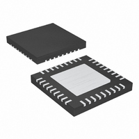
MAX9742ETX+ Maxim Integrated Products, MAX9742ETX+ Datasheet - Page 14

MAX9742ETX+
Manufacturer Part Number
MAX9742ETX+
Description
IC AMP AUDIO PWR 20.5W D 36TQFN
Manufacturer
Maxim Integrated Products
Type
Class Dr
Datasheet
1.MAX9742ETX.pdf
(36 pages)
Specifications of MAX9742ETX+
Output Type
2-Channel (Stereo)
Max Output Power X Channels @ Load
20.5W x 2 @ 8 Ohm
Voltage - Supply
20 V ~ 40 V, ±10 V ~ 20 V
Features
Depop, Differential Inputs, Mute, Short-Circuit and Thermal Protection, Shutdown
Mounting Type
Surface Mount
Package / Case
36-TQFN Exposed Pad
Product
Class-D
Output Power
16 W
Thd Plus Noise
0.08 %
Supply Current
15 mA
Maximum Power Dissipation
2.86 W
Maximum Operating Temperature
+ 85 C
Mounting Style
SMD/SMT
Audio Load Resistance
4 Ohms
Minimum Operating Temperature
- 40 C
Lead Free Status / RoHS Status
Lead free / RoHS Compliant
efficiency of a linear amplifier is 78%; however, that effi-
ciency is only exhibited at peak output powers. Under
normal operating levels (typical music reproduction lev-
els), efficiency falls below 30%, whereas the MAX9742
still exhibits 80% efficiency under the same conditions.
Since the output transistors switch the output to either
V
resulting output of a Class D amplifier is a high-fre-
quency square wave. This square wave is pulse-width-
modulated by the audio input signal. In the MAX9742,
the pulse-width modulation (PWM) is accomplished by
comparing the input audio signal to an internally gener-
ated triangle wave oscillator. The resulting duty cycle of
Single-/Dual-Supply, Stereo 16W,
Class D Amplifier with Differential Inputs
Figure 2. Simplified Block Diagram of the MAX9742 Output Stage
14
DD
______________________________________________________________________________________
or V
SS
(ground for single-supply operation), the
CONNECTED TO V
DUAL-SUPPLY CONFIGURATION SHOWN
(INTERNALLY
NSENSE
MAX9742
SS
)
(WITH RESPECT TO V
C
REGLS
1µF
GATE DRIVE LOGIC
7V REGULATOR
REGLS
1N4148
SS
D
BOOT
)
V
REGLS
V
SS
the square wave is proportional to the level of the input
signal. When the input signal is at 0V, the duty cycle of
the MAX9742 output is equal to 50%. To extract the
amplified audio signal from this PWM waveform, the
output of the MAX9742 is fed to an external LC lowpass
filter (see the Single-Ended LC Output Filter Design (L
and C
circuit for the PWM output voltage waveform. The
resulting averaged output voltage is equal to the ampli-
fied audio signal. Figure 3a illustrates the resulting
PWM output waveform due to the varying input signal
level, and Figure 3b shows the recovered amplified
input signal after filtering.
C
0.1µF
BOOT
V
V
DD
SS
F
) section). The LC filter works as an averaging
OUT_
L
F
C
F
F


