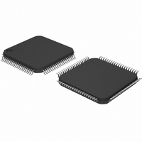
SC28L194A1BE,551 NXP Semiconductors, SC28L194A1BE,551 Datasheet - Page 18

SC28L194A1BE,551
Manufacturer Part Number
SC28L194A1BE,551
Description
IC UART QUAD W/FIFO 80-LQFP
Manufacturer
NXP Semiconductors
Datasheet
1.SC28L194A1BE528.pdf
(52 pages)
Specifications of SC28L194A1BE,551
Features
False-start Bit Detection
Number Of Channels
4, QUART
Fifo's
16 Byte
Voltage - Supply
3.3V, 5V
With Auto Flow Control
Yes
With False Start Bit Detection
Yes
With Modem Control
Yes
With Cmos
Yes
Mounting Type
Surface Mount
Package / Case
80-LQFP
Lead Free Status / RoHS Status
Lead free / RoHS Compliant
Other names
935262730551
SC28L194A1BE-S
SC28L194A1BE-S
SC28L194A1BE-S
SC28L194A1BE-S
Available stocks
Company
Part Number
Manufacturer
Quantity
Price
Company:
Part Number:
SC28L194A1BE,551
Manufacturer:
NXP Semiconductors
Quantity:
10 000
Philips Semiconductors
Table 4. MR1 - Mode Register 1
MR1[7]: Receiver Request to Send Control
This bit controls the deactivation of the RTSN output (I/O2) by the
receiver. This output is asserted and negated by commands applied
via the command register. MR1[7] = 1 causes RTSN to be
automatically negated upon receipt of a valid start bit if the receiver
FIFO is 3/4 full or greater. RTSN is reasserted when an the FIFO fill
level falls below 3/4 full. This constitutes a change from previous
members of Philips (Signets)’ UART families where the RTSN
function triggered on FIFO full. This behavior caused problems with
PC UARTs that could not stop transmission at the proper time. The
RTSN feature can be used to prevent overrun in the receiver, by
using the RTSN output signal, to control the CTSN input of the
transmitting device.
MR1[6]: Interrupt Status Masking
This bit controls the readout mode of the Interrupt Status Register,
ISR. If set, the ISR reads the current status masked by the IMR, i.e.
only interrupt sources enabled in the IMR can ever show a ‘1’ in the
ISR. If cleared, the ISR shows the current status of the interrupt
source without regard to the Interrupt Mask setting.
MR1[5]: Error Mode Select
This bit selects the operating mode of the three FIFOed status bits
(FE, PE, received break). In the character mode, status is provided
2006 Aug 15
RxRTS Control
0 - off
1 - on
Quad UART for 3.3 V and 5 V supply voltage
Bit 7
ISR Read Mode
0 - ISR unmasked
1 - ISR masked
Bit 6
Error Mode
0 = Character
1 = Block
Bit 5
18
Parity Mode
00 - With Parity
01 - Force parity
10 - No parity
11 - Special Mode
on a character by character basis; the status applies only to the
character at. the bottom of the FIFO. In the block mode, the status
provided in the SR for these bits is the accumulation (logical OR) of
the status for all characters coming to the top of the FIFO, since the
last reset error command was issued.
MR1[4:3]: Parity Mode Select
If ‘with parity’ or ’force parity’ is selected, a parity bit is added to the
transmitted character and the receiver performs a parity check on
incoming data. MR1[4:3] = 11 selects the channel to operate in the
special Wake-up mode.
MR1[2]: Parity Type Select
This bit sets the parity type (odd or even) if the ’with parity’ mode is
programmed by MR1[4:3], and the polarity of the forced parity bit if
the ’force parity’ mode is programmed. It has no effect if the ’no
parity’ mode is programmed. In the special ’Wake-up’ mode, it
selects the polarity of the A/D bit. The parity bit is used to an
address or data byte in the ’Wake-up’ mode.
MR1[1:0]: Bits per Character Select
This field selects the number of data bits per character to be
transmitted and received. This number does not include the start,
parity, or stop bits.
Bit 4:3
Parity Type
0 = Even
1 = Odd
Bit 2
Bits per Character
00 - 5
01 - 6
10 - 7
11 - 8
SC28L194
Product data sheet
Bit 1:0


