STD12NE06 STMicroelectronics, STD12NE06 Datasheet
STD12NE06
Specifications of STD12NE06
Available stocks


Related parts for STD12NE06


STD12NE06 Summary of contents
Page 1
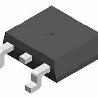
... Peak Diode Recovery voltage slope 1 T Storage T emperature Max. Operating Junction Temperature Pulse width limited by safe operating area March 1999 IPAK TO-251 Feature (Suffix ”-1”) INTERNAL SCHEMATIC DIAGRAM = 100 di/dt 200 STD12NE06 POWER MOSFET DPAK TO-252 (Suffix ”T4”) Value Unit 0. V/ns o -65 to 175 C o ...
Page 2
... STD12NE06 THERMAL DATA R Thermal Resistance Junction-case thj -case R Thermal Resistance Junction-ambient thj -amb R Thermal Resistance Case-sink thc-sink T Maximum Lead Temperature F or Soldering Purpose l AVALANCHE CHARACTERISTICS Symbo l I Avalanche Current, Repetitive or Not-Repetitive AR (pulse width limited Single Pulse Avalanche Energy AS o (starting ELECTRICAL CHARACTERISTICS (T ...
Page 3
... Test Con ditions 4 (see test circuit, figure Test Con ditions 4 (see test circuit, figure 5) Test Con ditions di/dt = 100 150 (see test circuit, figure 5) Thermal Impedance STD12NE06 Min. Typ. Max. Unit Min. Typ. Max. Unit Min. Typ. Max. Unit 1 0. 3/10 ...
Page 4
... STD12NE06 Derating Curve Transfer Characteristics Static Drain-source On Resistance 4/10 Output Characteristics Transconductance Gate Charge vs Gate-source Voltage ...
Page 5
... Capacitance Variations Normalized On Resistance vs Temperature Turn-off Drain-source Voltage Slope STD12NE06 Normalized Gate Threshold Voltage vs Temperature Turn-on Current Slope Cross-over Time 5/10 ...
Page 6
... STD12NE06 Switching Safe Operating Area Source-drain Diode Forward Characteristics Fig. 1: Unclamped Inductive Load Test Circuit 6/10 Accidental Overload Area Fig. 2: Unclamped Inductive Waveform ...
Page 7
... Fig. 3: Switching Times Test Circuits For Resistive Load Fig. 5: Test Circuit For Inductive Load Switching And DIode Recovery Times STD12NE06 Fig. 4: Gate Charge test Circuit 7/10 ...
Page 8
... STD12NE06 TO-251 (IPAK) MECHANICAL DATA DIM. MIN. TYP. A 2.2 A1 0.9 A3 0.7 B 0. 0. 6.4 G 4 8/10 mm MAX. MIN. 2.4 0.086 1.1 0.035 1.3 0.027 0.9 0.025 5.4 0.204 0.85 0.3 0.95 0.6 0.017 0.6 0.019 6.2 0.236 6.6 ...
Page 9
... DETAIL ”A” L4 STD12NE06 inch TYP. MAX. 0.094 0.043 0.009 0.035 0.212 0.023 0.023 0.244 0.260 0.181 0.397 0.031 0.039 0068772-B 9/10 ...
Page 10
... STD12NE06 Information furnished is believed to be accurate and reliable. However, STMicroelect r onics assumes no responsibil ity for the consequences of use of such information nor for any infringement of patents or other rights of third part i es which may result from its use. No license is granted by implication or otherwise under any patent or patent rights of STMicroelectro nics. Specific ation mentioned in this publication are subjec t to change without notice ...