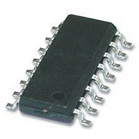
ADM3052BRWZ Analog Devices Inc, ADM3052BRWZ Datasheet - Page 4

ADM3052BRWZ
Manufacturer Part Number
ADM3052BRWZ
Description
58T4518
Manufacturer
Analog Devices Inc
Specifications of ADM3052BRWZ
Interface Type
CAN
No. Of Rx Buffers
1
Digital Ic Case Style
SOIC
No. Of Pins
16
Operating Temperature Range
-40°C To +85°C
Rohs Compliant
Yes
Number Of Transmitters
1
Power Supply Requirement
Dual
Operating Temperature Classification
Industrial
Mounting
Surface Mount
Operating Temperature (max)
85C
Operating Temperature (min)
-40C
Lead Free Status / Rohs Status
Compliant
Available stocks
Company
Part Number
Manufacturer
Quantity
Price
Company:
Part Number:
ADM3052BRWZ
Manufacturer:
ADI
Quantity:
68
Part Number:
ADM3052BRWZ
Manufacturer:
ADI/亚德诺
Quantity:
20 000
Part Number:
ADM3052BRWZ-REEL7
Manufacturer:
ADI/亚德诺
Quantity:
20 000
ADM3052
TIMING SPECIFICATIONS
All voltages are relative to their respective ground; 3.0 V ≤ V
Table 2.
Parameter
DRIVER
RECEIVER
POWER-UP
REGULATORY INFORMATION
The
Table 3.
Organization
UL
VDE
INSULATION AND SAFETY-RELATED SPECIFICATIONS
Table 4.
Parameter
Rated Dielectric Insulation Voltage
Minimum External Air Gap (Clearance)
Minimum External Tracking (Creepage)
Minimum Internal Gap (Internal Clearance)
Tracking Resistance (Comparative Tracking Index)
Isolation Group
Maximum Data Rate
Propagation Delay from TxD On to Bus Active
Propagation Delay from TxD Off to Bus Inactive
Propagation Delay from TxD On to Receiver Active
Propagation Delay from TxD Off to Receiver Inactive
Enable Time, V
Disable Time, V
ADM3052
approval is pending by the organizations listed in Table 3.
+
Approval Type
Recognized under the component recognition
program of Underwriters Laboratories, Inc.
Certified according to DIN V VDE V 0884-10
(VDE V 0884-10):2006-12
+
High to V
Low to V
+SENSE
+SENSE
Low
High
Symbol
L(I01)
L(I02)
CTI
DD1
Rev. 0 | Page 4 of 20
Symbol
t
t
t
t
t
t
≤ 5.5 V, T
onTxD
offTxD
onRxD
offRxD
SE
SD
Value
5000
7.7
7.6
0.017 min
>175
IIIa
In accordance with UL 1577, each
applying an insulation test voltage ≥6000 V rms for 1 second
(current leakage detection limit = 10 μA)
In accordance with DIN V VDE V 0884-10, each
tested by applying an insulation test voltage ≥1590 V peak for
1 second (partial discharge detection limit = 5 pC)
Notes
A
= −40°C to +85°C, V
Min
1
Unit
V rms
mm
mm
mm
V
Typ
Conditions
1-minute duration
Measured from input terminals to output terminals,
shortest distance through air
Measured from input terminals to output terminals,
shortest distance along body
Insulation distance through insulation
DIN IEC 112/VDE 0303-1
Material group (DIN VDE 0110)
Max
90
120
200
250
300
10
+
= 11 V to 25 V, unless otherwise noted.
Unit
Mbps
ns
ns
ns
ns
μs
ms
ADM3052
Test Conditions
See Figure 25 and Figure 27,
R
See Figure 25 and Figure 27,
R
See Figure 25 and Figure 27,
R
See Figure 25 and Figure 27,
R
See Figure 29
See Figure 29
L
L
L
L
= 60 Ω, C
= 60 Ω, C
= 60 Ω, C
= 60 Ω, C
is proof tested by
ADM3052
L
L
L
L
= 100 pF
= 100 pF
= 100 pF
= 100 pF
is proof


