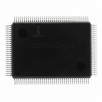
ISL54102ACQZ Intersil, ISL54102ACQZ Datasheet - Page 9

ISL54102ACQZ
Manufacturer Part Number
ISL54102ACQZ
Description
IC TMDS REGEN W/MUX 128-MQFP
Manufacturer
Intersil
Datasheet
1.ISL54101ACQZ.pdf
(21 pages)
Specifications of ISL54102ACQZ
Applications
Multimedia Displays, Test Equipment
Interface
I²C
Voltage - Supply
3 V ~ 3.6 V
Package / Case
128-MQFP, 128-PQFP
Mounting Type
Surface Mount
Rohs Compliant
Yes
Lead Free Status / RoHS Status
Lead free / RoHS Compliant
Available stocks
Company
Part Number
Manufacturer
Quantity
Price
Company:
Part Number:
ISL54102ACQZ
Manufacturer:
INTERSIL
Quantity:
2 370
Part Number:
ISL54102ACQZ
Manufacturer:
INTERSIL
Quantity:
20 000
Register Listing
0x00
0x01
0x02
ADDRESS
Device ID (read only)
Channel Activity Detect (read only)
Channel Selection (0x0C)
REGISTER (DEFAULT VALUE)
9
ISL54100A, ISL54101A, ISL54102A
BIT(S)
3:0
7:4
1:0
0
1
2
3
2
3
4
5
Device Revision
Device ID
Channel A Active
Channel B Active
Channel C Active
Channel D Active
Auto Channel Select 0: Manual Channel Select (using bits 0 and 1).
Hardware Channel
Select
Reset
Power-down
Channel Select
FUNCTION NAME
1 = initial silicon, 2 = second revision, etc.
3 = ISL5410xA
0: TMDS clock not present on Channel A
1: TMDS clock detected on Channel A
0: TMDS clock not present on Channel B
1: TMDS clock detected on Channel B
0: TMDS clock not present on Channel C
1: TMDS clock detected on Channel C
0: TMDS clock not present on Channel D
1: TMDS clock detected on Channel D
Selects the input channel for the mux. These 2 bits are Read
Only if Auto Channel Select is enabled.
0: Channel A selected
1: Channel B selected
2: Channel C selected
3: Channel D selected
1: Auto Channel Select. Mux always selects the active
channel with the highest priority. A = 1st (highest), B = 2nd,
C = 3rd, D = 4th (lowest) priority.
An active channel is a channel that has clock activity on its
TMDS clock lines. If no channels are active, the A channel
is selected. (default)
0: Software channel selection (using bits 0-2 of this register)
1: Hardware channel selection (using “Auto Channel Select”
and “CH Sel 0/1” external pins) (default)
Full chip reset. Write a 1 to reset. Will set itself to 0 when
reset is complete.
0: Normal Operation
1: Puts the chip in a minimal power consumption mode,
turning off all TMDS outputs and open-circuiting all TMDS
inputs.
This bit is OR'ed with the Power-down input pin. If either is
set, the chip will enter power-down. Serial
I/O stays operational in PD mode.
Note: When exiting Power-down, a termination resistor
Recalibration cycle must be run to re-trim the termination
resistors (see register 0x03[7]).
DESCRIPTION
June 17, 2008
FN6725.0


