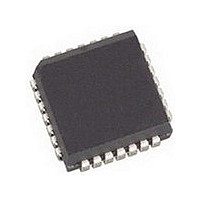
AMIS49587C5871RG ON Semiconductor, AMIS49587C5871RG Datasheet - Page 11

AMIS49587C5871RG
Manufacturer Part Number
AMIS49587C5871RG
Description
IC MODEM PLC 50/60MHZ 28PLCC
Manufacturer
ON Semiconductor
Specifications of AMIS49587C5871RG
Baud Rates
Selectable
Interface
SCI
Voltage - Supply
3 V ~ 3.6 V
Mounting Type
Surface Mount
Package / Case
28-PLCC
Number Of Transmitters
1
Power Supply Requirement
Single
Package Type
PLCC
Operating Temperature Classification
Commercial
Mounting
Surface Mount
Pin Count
28
Operating Temperature (max)
70C
Dual Supply Voltage (typ)
Not RequiredV
Dual Supply Voltage (max)
Not RequiredV
Dual Supply Voltage (min)
Not RequiredV
Lead Free Status / RoHS Status
Lead free / RoHS Compliant
Data Format
-
Lead Free Status / Rohs Status
Compliant
Available stocks
Company
Part Number
Manufacturer
Quantity
Price
Company:
Part Number:
AMIS49587C5871RG
Manufacturer:
ON
Quantity:
3 400
Company:
Part Number:
AMIS49587C5871RG
Manufacturer:
ON Semiconductor
Quantity:
10 000
4.1
4.1.1 Oscillator: Pin XIN, XOUT
In production the actual oscillation of the oscillator and duty cycle will not be tested. The production test will be based on the
static parameters and the inversion from XIN to XOUT in order to guarantee the functionality of the oscillator.
1. Guaranteed by design. Maximum allowed series loss resistance up to 80 Ω.
4.1.2 Zero Crossing Detector and 50/60 Hz PLL: Pin M50HZ_IN
2. Measured relative to V
3. These parameters will not be measured in production since the performance is totally dependent of a digital circuit which will be guaranteed
Table 8. OSCILLATOR
Table 9. ZERO CROSSING DETECTOR AND 50/60 Hz PLL
Crystal frequency
Duty cycle with quartz connected
Start--up time
Maximum Capacitive load on XOUT
Low input threshold voltage
High input threshold voltage
Low output voltage
High input voltage
Maximum peak input current
Maximum average input current
Mains voltage (ms) range
Rising threshold level
Falling threshold level
Hysteresis
Lock range for 50 Hz (Note 3)
Lock range for 60 Hz (Note 3)
Lock time (Note 3)
Lock time (Note 3)
Frequency variation without going out of
lock (Note 3)
Frequency variation without going out of
lock (Note 3)
Jitter of CHIP_CLK (Note 3)
by the digital test patterns.
DC AND AC CHARACTERISTICS
Parameter
Parameter
SS
.
4 ELECTRICAL CHARACTERISTICS
(Note 1)
(Note 1)
(Note 1)
XIN used as clock input
XIN used as clock input
XIN used as clock input
XIN used as clock input,
XOUT = 2 mA
XIN used as clock input
During 1 ms
With protection resistor at
M50HZIN
(Note 2)
(Note 2)
(Note 2)
MAINS_FREQ = 0 (50 Hz)
MAINS_FREQ = 0 (60 Hz)
MAINS_FREQ = 0 (50 Hz)
MAINS_FREQ = 0 (60 Hz)
MAINS_FREQ = 0 (50 Hz)
MAINS_FREQ = 0 (60 Hz)
Test Conditions
Test Conditions
http://onsemi.com
11
Imavg
Jitter
VIRM
Imp
VIFM
VHY
VOH
VOL
Flock
Flock
Tlock
Tlock
VIH
VIL
Symbol
Symbol
CL
V
DF
DF
T
f
startup
MAINS
M50HZIN
CHIP_CLK
CLK
XOUT
XOUT
M50HZIN
50HZIN
XOUT
60Hz
50Hz
50HZIN
XOUT
50HZIN
XOUT
50Hz
60Hz
50Hz
60Hz
--100 ppm
0.3 V
Min
Min
--20
--25
0.9
0.4
40
--2
90
45
54
DD
Typ
Typ
24
+100 ppm
V
0.7 V
DD
Max
Max
550
0.3
1.9
0.1
0.1
60
50
50
20
55
66
15
20
25
2
--0.3
DD
MHz
Hz/s
Hz/s
Unit
Unit
mA
mA
ms
pF
Hz
Hz
ms
%
V
V
V
V
V
V
V
V
s
s


