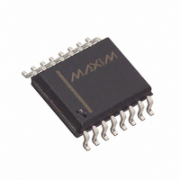
MAX7329AWE+T Maxim Integrated Products, MAX7329AWE+T Datasheet - Page 8

MAX7329AWE+T
Manufacturer Part Number
MAX7329AWE+T
Description
IC I/O EXPANDER I2C 8B 16SOIC
Manufacturer
Maxim Integrated Products
Datasheet
1.MAX7329AWE.pdf
(13 pages)
Specifications of MAX7329AWE+T
Interface
I²C
Number Of I /o
8
Interrupt Output
Yes
Frequency - Clock
100KHz
Voltage - Supply
2.5 V ~ 5.5 V
Operating Temperature
-40°C ~ 125°C
Mounting Type
Surface Mount
Package / Case
16-SOIC (0.300", 7.5mm Width)
Lead Free Status / RoHS Status
Lead free / RoHS Compliant
The first (A6), second (A5), third (A4), and fourth (A3)
bits of the MAX7328 slave address are always 0, 1, 0,
and 0. Slave address bits A2, A1, and A0 are selected
by the address inputs AD2, AD1, and AD0. These pins
can be connected to GND or V+. The MAX7328 has
eight possible slave addresses (Table 1), and there-
fore, a maximum of eight MAX7328 devices can be
controlled independently from the same interface.
The first (A6), second (A5), third (A4), and fourth (A3)
bits of the MAX7329 slave address are always 0, 1, 1,
and 1. Slave address bits A2, A1, and A0 are selected
by the address inputs AD2, AD1, and AD0. These pins
can be connected to GND or V+. The MAX7329 has
eight possible slave addresses (Table 2), and therefore,
a maximum of eight MAX7329 devices can be controlled
independently from the same interface.
Because the MAX7328 has a different range of slave
address selections than the MAX7329, a total of eight
MAX7328 devices and eight MAX7329 devices can be
connected to the same bus and independently controlled.
I
follows:
A single-byte read from the MAX7328 or MAX7329
returns the status of the eight ports (with output ports
read back as inputs), and clears the INT output.
A 2-byte read from the MAX7328 or MAX7329 returns
the status of the eight ports (with output ports read
back as inputs) and clears the INT output.
I
8
Figure 8. Reading from the MAX7328/MAX7329 (1 Data Byte)
2
C interface access to the MAX7328/MAX7329 is as
2
_______________________________________________________________________________________
C Port Expanders with Eight I/O Ports
t
IV
INT OUTPUT
PORT INPUT DATA
SCL
the MAX7328 and MAX7329
S
MAX7328/MAX7329 SLAVE ADDRESS
Reading and Writing
DATA 1
PORT SNAPSHOT DATA
R/W
1
S = START CONDITION
P = STOP CONDITION
A
t
IR
t
PH
PORT SNAPSHOT TAKEN
A multibyte read repeatedly returns the input port data.
Input port data is sampled during the preceding I
acknowledge bit, which is the acknowledge bit for the
I
2-byte read.
A single-byte write to the MAX7328 or MAX7329 sets
the eight ports to high or low, depending on the data
byte content. Bit locations of a write byte, corresponding
to ports intended for input usage, contain high values.
A multibyte write to the MAX7328 or MAX7329 repeat-
edly sets the logic state of all eight I/O ports.
A read from the MAX7328 or MAX7329 starts with the
master transmitting the MAX7328’s or MAX7329’s slave
address with the R/W bit set high. The MAX7328 or
MAX7329 acknowledges the slave address, and samples
the input ports (takes a snapshot) during acknowledge.
Typically, the master reads 1 or 2 bytes from the MAX7328
or MAX7329, each byte being acknowledged by the mas-
ter on reception, with exception of the last byte.
The master can read 1 byte from the MAX7328 or
MAX7329 and then issue a STOP condition (Figure 8). In
this case, the MAX7328 or MAX7329 transmits the cur-
rent port data, and restarts the transition detection. INT
goes high (high impedance if an external pullup resistor
is not fitted) during the port data-byte acknowledge. The
new snapshot data is the current port data transmitted
to the master, and therefore, any port changes that
P7
D7
2
C slave address in the case of a single-byte or
t
IV
P6
DATA 2
D6
P5
D5
Reading from the MAX7328
P4
DATA 1
D4
SHADED = SLAVE TRANSMISSION
N = NOT ACKNOWLEDGE
P3
PORT SNAPSHOT TAKEN
D3
DATA 3
P2
D2
P1
D1
P0
D0
t
PSU
and MAX7329
N
t
IR
P
2
C


