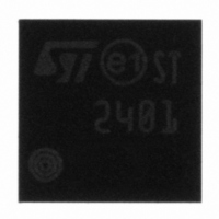
STMPE2401TBR STMicroelectronics, STMPE2401TBR Datasheet - Page 27

STMPE2401TBR
Manufacturer Part Number
STMPE2401TBR
Description
IC I/O EXPANDER I2C 24B 36TFBGA
Manufacturer
STMicroelectronics
Datasheet
1.STMPE2401TBR.pdf
(55 pages)
Specifications of STMPE2401TBR
Interface
I²C
Number Of I /o
24
Interrupt Output
Yes
Frequency - Clock
400kHz
Voltage - Supply
1.65 V ~ 1.95 V
Operating Temperature
-40°C ~ 85°C
Mounting Type
Surface Mount
Package / Case
36-TFBGA
Includes
Keypad, POR, PWM
For Use With
497-6426 - BOARD EVAL BASED ON STMPE2401
Lead Free Status / RoHS Status
Lead free / RoHS Compliant
Other names
497-6133-2
Available stocks
Company
Part Number
Manufacturer
Quantity
Price
Company:
Part Number:
STMPE2401TBR
Manufacturer:
STMicroelectronics
Quantity:
10 000
Part Number:
STMPE2401TBR
Manufacturer:
ST
Quantity:
20 000
STMPE2401
9.7
Programming sequence
To configure and initialize the Interrupt Controller to allow interruption to host, observe the
following steps:
●
●
●
●
●
●
●
●
●
●
●
Set the IER and IEGPIOR registers to the desired values to enable the interrupt
sources that are to be expected to receive from.
Configure the output interrupt type and polarity and enable the global interrupt mask by
writing to the ICR.
Wait for interrupt.
Upon receiving an interrupt, the INT pin is asserted.
The host comes to read the ISR through I
that the corresponding interrupt source is triggered.
If the IS8 bit in ISR is set, the interrupt is coming from the GPIO Controller. Then, a
subsequent read is performed on the ISGPIOR to obtain the interrupt status of all 16
GPIOs to locate the GPIO that triggers the interrupt. This is a feature so-called ‘Hot
Key’.
After obtaining the interrupt source that triggers the interrupt, the host performs the
necessary processing and operations related to the interrupt source.
If the interrupt source is from the GPIO Controller, two write operations with value of ‘1’
are performed to the ISG[x] bit (ISGPIOR) and the IS[8] (ISR) to clear the
corresponding GPIO interrupt.
If the interrupt source is from other module, a write operation with value of ‘1’ is
performed to the IS[x] (ISR) to clear the corresponding interrupt.
Once the interrupt is being cleared, the INT pin will also be de-asserted if the interrupt
type is level interrupt. An edge interrupt will only assert a pulse width of 250ns.
When the interrupt is no longer required, the IC0 bit in ICR may be set to ‘0’ to disable
the global interrupt mask bit.
2
C interface. A ‘1’ in the ISR bits indicates
Interrupt system
27/55


