DS21FF42 Maxim Integrated Products, DS21FF42 Datasheet - Page 67
DS21FF42
Manufacturer Part Number
DS21FF42
Description
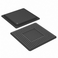
IC FRAMER T1 4X4 16CH 300-BGA
Manufacturer
Maxim Integrated Products
Datasheet
1.DS21FT42.pdf
(114 pages)
Specifications of DS21FF42
Controller Type
T1 Framer
Interface
Parallel/Serial
Voltage - Supply
2.97 V ~ 3.63 V
Current - Supply
300mA
Operating Temperature
0°C ~ 70°C
Mounting Type
Surface Mount
Package / Case
300-BGA
Lead Free Status / RoHS Status
Contains lead / RoHS non-compliant
Available stocks
Company
Part Number
Manufacturer
Quantity
Price
Company:

Part Number:
DS21FF42
Manufacturer:
LATTRON
Quantity:
9 020


RECEIVE A HDLC MESSAGE OR A BOC
1. Enable RBOC and RPS interrupts
2. Wait for interrupt to occur
3. If RBOC=1, then follow steps 5 and 6
4. If RPS=1, then follow steps 7 through 12
5. If LBD=1, a BOC is present, then read the code from the RBOC register and take action as needed
6. If BD=0, a BOC has ceased, take action as needed and then return to step 1
7. Disable RPS interrupt and enable either RPE, RNE, or RHALF interrupt
8. Read RHIR to obtain REMPTY status a. if REMPTY=0, then record OBYTE, CBYTE, and POK bits
9. Repeat step 8
10. Wait for interrupt, skip to step 8
11. If POK=0, then discard whole packet, if POK=1, accept the packet 12, disable RPE, RNE, or RHALF
TRANSMIT A HDLC MESSAGE
1. Make sure HDLC controller is done sending any previous messages and is current sending flags by
2. Enable either the THALF or TNF interrupt
3. Read THIR to obtain TFULL status a. if TFULL=0, then write a byte into the FIFO and skip to next
4. Repeat step 3
5. Wait for interrupt, skip to step 3
6. Disable THALF or TNF interrupt and enable TMEND interrupt
7. Wait for an interrupt, then read TUDR status bit to make sure packet was transmitted correctly.
TRANSMIT A BOC
1. Write 6–bit code into TBOC
2. Set SBOC bit in TBOC=1
19.1.3 HDLC/BOC Register Description
HCR: HDLC CONTROL REGISTER (Address = 00 Hex)
(MSB)
and then read the FIFO a1. if CBYTE=0 then skip to step 9 a2. if CBYTE=1 then skip to step 11 b. if
REMPTY=1, then skip to step 10
interrupt, enable RPS interrupt and return to step 1.
checking that the FIFO is empty by reading the TEMPTY status bit in the THIR register
step (special case occurs when the last byte is to be written, in this case set TEOM=1 before writing
the byte and then skip to step 6) b. if TFULL=1, then skip to step 5
RBR
SYMBOL
RHR
RBR
RHR
POSITION
HCR.7
HCR.6
TFS
NAME AND DESCRIPTION
Receive BOC Reset. A 0 to 1 transition will reset the BOC
circuitry. Must be cleared and set again for a subsequent
reset.
Receive HDLC Reset. A 0 to 1 transition will reset the
HDLC controller. Must be cleared and set again for a
subsequent reset.
THR
67 of 114
TABT
TEOM
TZSD
TCRCD
(LSB)
Related parts for DS21FF42
Image
Part Number
Description
Manufacturer
Datasheet
Request
R

Part Number:
Description:
MAX7528KCWPMaxim Integrated Products [CMOS Dual 8-Bit Buffered Multiplying DACs]
Manufacturer:
Maxim Integrated Products
Datasheet:
Part Number:
Description:
Single +5V, fully integrated, 1.25Gbps laser diode driver.
Manufacturer:
Maxim Integrated Products
Datasheet:
Part Number:
Description:
Single +5V, fully integrated, 155Mbps laser diode driver.
Manufacturer:
Maxim Integrated Products
Datasheet:
Part Number:
Description:
VRD11/VRD10, K8 Rev F 2/3/4-Phase PWM Controllers with Integrated Dual MOSFET Drivers
Manufacturer:
Maxim Integrated Products
Datasheet:
Part Number:
Description:
Highly Integrated Level 2 SMBus Battery Chargers
Manufacturer:
Maxim Integrated Products
Datasheet:
Part Number:
Description:
Current Monitor and Accumulator with Integrated Sense Resistor; ; Temperature Range: -40°C to +85°C
Manufacturer:
Maxim Integrated Products
Part Number:
Description:
TSSOP 14/A�/RS-485 Transceivers with Integrated 100O/120O Termination Resis
Manufacturer:
Maxim Integrated Products
Part Number:
Description:
TSSOP 14/A�/RS-485 Transceivers with Integrated 100O/120O Termination Resis
Manufacturer:
Maxim Integrated Products
Part Number:
Description:
QFN 16/A�/AC-DC and DC-DC Peak-Current-Mode Converters with Integrated Step
Manufacturer:
Maxim Integrated Products
Part Number:
Description:
TDFN/A/65V, 1A, 600KHZ, SYNCHRONOUS STEP-DOWN REGULATOR WITH INTEGRATED SWI
Manufacturer:
Maxim Integrated Products
Part Number:
Description:
Integrated Temperature Controller f
Manufacturer:
Maxim Integrated Products
Part Number:
Description:
SOT23-6/I�/45MHz to 650MHz, Integrated IF VCOs with Differential Output
Manufacturer:
Maxim Integrated Products
Part Number:
Description:
SOT23-6/I�/45MHz to 650MHz, Integrated IF VCOs with Differential Output
Manufacturer:
Maxim Integrated Products
Part Number:
Description:
EVALUATION KIT/2.4GHZ TO 2.5GHZ 802.11G/B RF TRANSCEIVER WITH INTEGRATED PA
Manufacturer:
Maxim Integrated Products
Part Number:
Description:
QFN/E/DUAL PCIE/SATA HIGH SPEED SWITCH WITH INTEGRATED BIAS RESISTOR
Manufacturer:
Maxim Integrated Products
Datasheet: