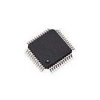
CS42324-CQZ Cirrus Logic Inc, CS42324-CQZ Datasheet - Page 33

CS42324-CQZ
Manufacturer Part Number
CS42324-CQZ
Description
IC CODEC STEREO AUDIO 48LQFP
Manufacturer
Cirrus Logic Inc
Type
Audio Codecr
Datasheet
1.CS42324-CQZ.pdf
(71 pages)
Specifications of CS42324-CQZ
Package / Case
48-LQFP
Data Interface
Serial
Resolution (bits)
24 b
Number Of Adcs / Dacs
1 / 2
Sigma Delta
Yes
Dynamic Range, Adcs / Dacs (db) Typ
95 / 100
Voltage - Supply, Analog
3.13 V ~ 3.47 V
Voltage - Supply, Digital
3.13 V ~ 3.47 V
Operating Temperature
-40°C ~ 85°C
Mounting Type
Surface Mount
Number Of Adc Inputs
1
Number Of Dac Outputs
2
Conversion Rate
96 KSPS
Interface Type
Serial (I2S, SPI)
Resolution
24 bit
Operating Supply Voltage
3.3 V
Maximum Operating Temperature
+ 85 C
Mounting Style
SMD/SMT
Minimum Operating Temperature
- 40 C
Number Of Channels
1 ADC/2 DAC
Supply Current
10 mA to 24 mA
Thd Plus Noise
- 88 dB ADC / - 90 dB DAC
Lead Free Status / RoHS Status
Lead free / RoHS Compliant
For Use With
598-1498 - BOARD EVAL FOR CS42324 CODEC
Lead Free Status / Rohs Status
Lead free / RoHS Compliant
Other names
598-1602
Available stocks
Company
Part Number
Manufacturer
Quantity
Price
Company:
Part Number:
CS42324-CQZ
Manufacturer:
TI
Quantity:
2 435
Company:
Part Number:
CS42324-CQZ
Manufacturer:
Cirrus Logic Inc
Quantity:
10 000
DS721A6
4.3
4.3.1
4.3.2
Analog-to-Digital Data Path
“Section 6.9 “ADC Control (Address 0Ah)” on page
put multiplexer. By default, line level input 1 is selected.
ADC Analog Input Multiplexer
AINxA and AINxB are the analog inputs, internally biased to VCMADC. The CS42324 contains a stereo
5-to-1 analog input multiplexer which can select one of 5 possible stereo analog input sources and route
it to the ADC.
ADC Description
The ADC analog modulator samples the input at 6.144 MHz (MCLK=12.288 MHz). The digital filter will
reject signals within the stopband of the filter. However, there is no rejection for input signals which are
(n
gram for the recommended analog input circuit that will attenuate noise energy at 6.144 MHz. The use of
capacitors which have a large voltage coefficient (such as general purpose ceramics) must be avoided
since these can degrade signal linearity. Any unused analog input pairs should be left unconnected.
The ADC output data is in two’s complement binary format. For inputs above positive full-scale or below
negative full-scale, the ADC will output 7FFFFFH or 800000H, respectively and cause the ADC overflow
bit to be set to a ‘1’.
Given the two’s complement format, low-level signals may cause the MSB of the serial data to periodically
toggle between ‘1’ and ‘0’, possibly introducing noise into the system as the bit switches back and forth.
To prevent this phenomena, a constant DC offset is added to the serial data bringing the low-level signal
just above the point at which the MSB would normally toggle, thus reducing the noise introduced. Note
that this offset is not removed (refer to
the specified offset level).
×
6.144 MHz) the digital passband frequency, where n=0,1,2,... Refer to the Typical Connection Dia-
Figure 16
shows the architecture of the input multiplexer.
Figure 16. Analog Input Architecture
AIN1A
AIN2A
AIN3A
AIN5A
AIN1B
AIN2B
AIN3B
AIN5B
AIN4A
AIN4B
“ADC Analog Characteristics - Commercial (-CQZ)” on page 17
AIN_SEL[2:0]
MUX
MUX
52” outlines the bit settings necessary to control the in-
Out to ADC
Channel A
Out to ADC
Channel B
CS42324
for
33


