MPC8560PX833LC Freescale Semiconductor, MPC8560PX833LC Datasheet - Page 20
MPC8560PX833LC
Manufacturer Part Number
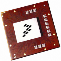
MPC8560PX833LC
Description
IC MPU PWRQUICC III 783-FCPBGA
Manufacturer
Freescale Semiconductor
Datasheet
1.MPC8560PX833LC.pdf
(104 pages)
Specifications of MPC8560PX833LC
Processor Type
MPC85xx PowerQUICC III 32-Bit
Speed
833MHz
Voltage
1.2V
Mounting Type
Surface Mount
Package / Case
783-FCPBGA
Family Name
MPC85XX
Device Core
PowerQUICC III
Device Core Size
32b
Frequency (max)
833MHz
Instruction Set Architecture
RISC
Supply Voltage 1 (typ)
1.2V
Operating Supply Voltage (max)
1.26V
Operating Supply Voltage (min)
1.14V
Operating Temp Range
0C to 105C
Operating Temperature Classification
Commercial
Mounting
Surface Mount
Pin Count
783
Package Type
FCBGA
For Use With
MPC8560ADS-BGA - BOARD APPLICATION DEV 8560
Lead Free Status / RoHS Status
Contains lead / RoHS non-compliant
Features
-
Lead Free Status / Rohs Status
Not Compliant
Available stocks
Company
Part Number
Manufacturer
Quantity
Price
Company:

Part Number:
MPC8560PX833LC
Manufacturer:
MOTOROLA
Quantity:
453
Company:
Part Number:
MPC8560PX833LC
Manufacturer:
Freescale Semiconductor
Quantity:
10 000
Part Number:
MPC8560PX833LC
Manufacturer:
FREESCALE
Quantity:
20 000


At recommended operating conditions with GV
DDR SDRAM
20
MCK[n] duty cycle
ADDR/CMD output valid
ADDR/CMD output invalid
Write CMD to first MDQS capture edge
MDQ/MECC/MDM output setup with respect to
MDQS
MDQ/MECC/MDM output hold with respect to
MDQS
MDQS preamble start
MDQS epilogue end
Notes:
1. The symbols used for timing specifications follow the pattern of t
2. All MCK/MCK referenced measurements are made from the crossing of the two signals ±0.1 V.
3. Maximum possible clock skew between a clock MCK[n] and its relative inverse clock MCK[n], or between a clock MCK[n] and
4. ADDR/CMD includes all DDR SDRAM output signals except MCK/MCK and MDQ/MECC/MDM/MDQS.
5. Note that t
6. Determined by maximum possible skew between a data strobe (MDQS) and any corresponding bit of data (MDQ), ECC
7. All outputs are referenced to the rising edge of MSYNC_IN (S) at the pins of the device. Note that t
8. Guaranteed by design.
9. Guaranteed by characterization.
inputs and t
(DD) from the rising or falling edge of the reference clock (KH or KL) until the output went invalid (OX or DX). For example,
t
(O) are valid (V) or output valid time. Also, t
(K) goes low (L) until data outputs (D) are invalid (X) or data output hold time.
a relative clock MCK[m] or MSYNC_OUT. Skew measured between complementary signals at GV
from the rising edge of the MSYNC_IN clock (SH) until the MDQS signal is valid (MH). t
control of the DQSS override bits in the TIMING_CFG_2 register. These controls allow the relationship between the
synchronous clock control timing and the source-synchronous DQS domain to be modified by the user. For best turnaround
times, these may need to be set to delay t
accordingly. See the MPC8560 PowerQUICC III Integrated Communications Processor Reference Manual for a description
and understanding of the timing modifications enabled by use of these bits.
(MECC), or data mask (MDM). The data strobe should be centered inside of the data eye at the pins of the device.
conventions described in note 1. For example, t
clock (SH) for the duration of the MDQS signal precharge period (MP).
DDKHOV
symbolizes DDR timing (DD) for the time t
DDSHMH
(first two letters of functional block)(reference)(state)(signal)(state)
Table 16. DDR SDRAM Output AC Timing Specifications–DLL Mode (continued)
Parameter
follows the symbol conventions described in note 1. For example, t
MPC8560 Integrated Processor Hardware Specifications, Rev. 5
333 MHz
266 MHz
200 MHz
333 MHz
266 MHz
200 MHz
DD
of 2.5 V ± 5%.
DDSHMH
DDKLDX
DDSHMP
t
MCKH
Symbol
t
t
t
t
t
MCK
t
t
t
t
an additional 0.25t
DDKHDS,
DDKHDX,
DDSHMH
DDSHMP
DDSHME
DDKHOV
DDKHOX
DDKLDS
DDKLDX
symbolizes DDR timing (DD) for the time t
describes the DDR timing (DD) from the rising edge of the MSYNC_IN
/t
memory clock reference (K) goes from the high (H) state until outputs
MCK
1
0.75 × t
(first two letters of functional block)(signal)(state) (reference)(state)
for outputs. Output hold time can be read as DDR timing
t
MCK
MCK
1100
1200
1100
1200
Min
900
900
1.5
45
—
MCK
1
+ 1.5
. This will also affect t
+ 1.5
DDSHMH
0.75 × t
DDSHMH
t
MCK
Max
describes the DDR timing (DD)
4.0
55
—
—
—
MCK
MCK
3
+ 4.0
DDSHMP
can be modified through
DDSHMP
+ 4.0
memory clock reference
DD
Freescale Semiconductor
/2.
and t
follows the symbol
Unit
DDSHME
ns
ns
ns
ps
ps
ns
ns
%
Notes
4, 9
4, 9
6, 9
6, 9
7, 8
7, 8
for
8
5
Related parts for MPC8560PX833LC
Image
Part Number
Description
Manufacturer
Datasheet
Request
R

Part Number:
Description:
Manufacturer:
Freescale Semiconductor, Inc
Datasheet:
Part Number:
Description:
Manufacturer:
Freescale Semiconductor, Inc
Datasheet:
Part Number:
Description:
Manufacturer:
Freescale Semiconductor, Inc
Datasheet:
Part Number:
Description:
Manufacturer:
Freescale Semiconductor, Inc
Datasheet:
Part Number:
Description:
Manufacturer:
Freescale Semiconductor, Inc
Datasheet:
Part Number:
Description:
Manufacturer:
Freescale Semiconductor, Inc
Datasheet:
Part Number:
Description:
Manufacturer:
Freescale Semiconductor, Inc
Datasheet:
Part Number:
Description:
Manufacturer:
Freescale Semiconductor, Inc
Datasheet:
Part Number:
Description:
Manufacturer:
Freescale Semiconductor, Inc
Datasheet:
Part Number:
Description:
Manufacturer:
Freescale Semiconductor, Inc
Datasheet:
Part Number:
Description:
Manufacturer:
Freescale Semiconductor, Inc
Datasheet:
Part Number:
Description:
Manufacturer:
Freescale Semiconductor, Inc
Datasheet:
Part Number:
Description:
Manufacturer:
Freescale Semiconductor, Inc
Datasheet:
Part Number:
Description:
Manufacturer:
Freescale Semiconductor, Inc
Datasheet:
Part Number:
Description:
Manufacturer:
Freescale Semiconductor, Inc
Datasheet: