XPC8260ZUIFBC Freescale Semiconductor, XPC8260ZUIFBC Datasheet - Page 36
XPC8260ZUIFBC
Manufacturer Part Number
XPC8260ZUIFBC
Description
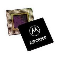
IC MPU POWERQUICC II 480-TBGA
Manufacturer
Freescale Semiconductor
Series
PowerQUICC IIr
Specifications of XPC8260ZUIFBC
Processor Type
MPC82xx PowerQUICC II 32-bit
Speed
200MHz
Voltage
2.5V
Mounting Type
Surface Mount
Package / Case
480-TBGA
Family Name
MPC82XX
Device Core
PowerQUICC II
Device Core Size
32b
Frequency (max)
200MHz
Instruction Set Architecture
RISC
Supply Voltage 1 (typ)
1.8V
Operating Supply Voltage (max)
1.9V
Operating Supply Voltage (min)
1.7V
Operating Temp Range
0C to 105C
Operating Temperature Classification
Commercial
Mounting
Surface Mount
Pin Count
480
Package Type
TBGA
Core Size
32 Bit
Program Memory Size
32KB
Cpu Speed
133MHz
Embedded Interface Type
I2C, MII, SPI, TDM, UTOPIA
Digital Ic Case Style
TBGA
No. Of Pins
480
Rohs Compliant
No
Lead Free Status / RoHS Status
Contains lead / RoHS non-compliant
Features
-
Lead Free Status / Rohs Status
Not Compliant
Available stocks
Company
Part Number
Manufacturer
Quantity
Price

Company:
Part Number:
XPC8260ZUIFBC
Manufacturer:
FREE
Quantity:
5 510
Company:
Part Number:
XPC8260ZUIFBC
Manufacturer:
Freescale Semiconductor
Quantity:
10 000
Part Number:
XPC8260ZUIFBC
Manufacturer:
FREESCALE
Quantity:
20 000


1
2
3
4
5
Pinout
Symbols used in
36
VCCSYN1
GNDSYN
SPARE1
SPARE4
SPARE5
SPARE6
THERMAL0
THERMAL1
I/O power
Core Power
Ground
Note:
Only on Rev C.2 silicon.
The default configuration of the CPM pins (PA[0–31], PB[4–31], PC[0–31], PD[4–31]) is input. To prevent excessive DC current,
it is recommended to either pull unused pins to GND or VDDH, or to configure them as outputs.
Must be pulled down or left floating.
Must be pulled down or left floating. However, if compatibility with HiP4 silicon is required, this pin must be pulled up or left
floating.
For information on how to use this pin, refer to MPC8260 PowerQUICC II Thermal Resistor Guide available at
www.freescale.com.
OVERBAR
UTM
3
3
4
3
MPC8260 PowerQUICC II Integrated Communications Processor Hardware Specifications, Rev. 2
5
5
Table 14
Symbol
are described in
Pin Name
Table 14. Pinout List (continued)
Table 15. Symbol Legend
Table
Signals with overbars, such as TA, are active low
Indicates that a signal is part of the UTOPIA master interface
15.
Meaning
B9
AB1
AE11
U5
AF25
V4
AA1
AG4
AG21, AG14, AG8, AJ1, AJ2, AH1,
AH2, AG3, AF4, AE5, AC27, Y27,
T27, P27, K26, G27, AE25, AF26,
AG27, AH28, AH29, AJ28, AJ29, C7,
C14, C16, C20, C23, E10, A28, A29,
B28, B29, C27, D26, E25, H3, M4,
T3, AA4, A1, A2, B1, B2, C3, D4, E5
U28, U29, K28, K29, A9, A19, B19,
M1, M2, Y1, Y2, AC1, AC2, AH19,
AJ19, AH10, AJ10, AJ5
AA5, AF21, AF14, AF8, AE7, AF11,
AE17, AE23, AC26, AB25, Y26, V25,
T26, R25, P26, M25, K27, H25, G26,
D7, D10, D14, D16, D20, D23, C9,
E11, E13, E15, E19, E22, B3, G5,
H4, K5, M3, P5, T4, Y5, AA2, AC3
Freescale Semiconductor
Ball
Related parts for XPC8260ZUIFBC
Image
Part Number
Description
Manufacturer
Datasheet
Request
R

Part Number:
Description:
Manufacturer:
Freescale Semiconductor, Inc
Datasheet:
Part Number:
Description:
Manufacturer:
Freescale Semiconductor, Inc
Datasheet:
Part Number:
Description:
Manufacturer:
Freescale Semiconductor, Inc
Datasheet:
Part Number:
Description:
Manufacturer:
Freescale Semiconductor, Inc
Datasheet:
Part Number:
Description:
Manufacturer:
Freescale Semiconductor, Inc
Datasheet:
Part Number:
Description:
Manufacturer:
Freescale Semiconductor, Inc
Datasheet:
Part Number:
Description:
Manufacturer:
Freescale Semiconductor, Inc
Datasheet:
Part Number:
Description:
Manufacturer:
Freescale Semiconductor, Inc
Datasheet:
Part Number:
Description:
Manufacturer:
Freescale Semiconductor, Inc
Datasheet:
Part Number:
Description:
Manufacturer:
Freescale Semiconductor, Inc
Datasheet:
Part Number:
Description:
Manufacturer:
Freescale Semiconductor, Inc
Datasheet:
Part Number:
Description:
Manufacturer:
Freescale Semiconductor, Inc
Datasheet:
Part Number:
Description:
Manufacturer:
Freescale Semiconductor, Inc
Datasheet:
Part Number:
Description:
Manufacturer:
Freescale Semiconductor, Inc
Datasheet:
Part Number:
Description:
Manufacturer:
Freescale Semiconductor, Inc
Datasheet: