XPC8260ZUIFBC Freescale Semiconductor, XPC8260ZUIFBC Datasheet - Page 11
XPC8260ZUIFBC
Manufacturer Part Number
XPC8260ZUIFBC
Description
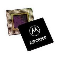
IC MPU POWERQUICC II 480-TBGA
Manufacturer
Freescale Semiconductor
Series
PowerQUICC IIr
Specifications of XPC8260ZUIFBC
Processor Type
MPC82xx PowerQUICC II 32-bit
Speed
200MHz
Voltage
2.5V
Mounting Type
Surface Mount
Package / Case
480-TBGA
Family Name
MPC82XX
Device Core
PowerQUICC II
Device Core Size
32b
Frequency (max)
200MHz
Instruction Set Architecture
RISC
Supply Voltage 1 (typ)
1.8V
Operating Supply Voltage (max)
1.9V
Operating Supply Voltage (min)
1.7V
Operating Temp Range
0C to 105C
Operating Temperature Classification
Commercial
Mounting
Surface Mount
Pin Count
480
Package Type
TBGA
Core Size
32 Bit
Program Memory Size
32KB
Cpu Speed
133MHz
Embedded Interface Type
I2C, MII, SPI, TDM, UTOPIA
Digital Ic Case Style
TBGA
No. Of Pins
480
Rohs Compliant
No
Lead Free Status / RoHS Status
Contains lead / RoHS non-compliant
Features
-
Lead Free Status / Rohs Status
Not Compliant
Available stocks
Company
Part Number
Manufacturer
Quantity
Price

Company:
Part Number:
XPC8260ZUIFBC
Manufacturer:
FREE
Quantity:
5 510
Company:
Part Number:
XPC8260ZUIFBC
Manufacturer:
Freescale Semiconductor
Quantity:
10 000
Part Number:
XPC8260ZUIFBC
Manufacturer:
FREESCALE
Quantity:
20 000


1
2
3
2.3.1
Each V
pin should likewise be provided with a low-impedance path to ground. The power supply pins drive
distinct groups of logic on chip. The V
0.1 µF by-pass capacitors located as close as possible to the four sides of the package. The capacitor leads
and associated printed circuit traces connecting to chip V
inch per capacitor lead. A four-layer board is recommended, employing two inner layers as V
planes.
All output pins on the MPC8260 have fast rise and fall times. Printed circuit (PC) trace interconnection
length should be minimized in order to minimize overdamped conditions and reflections caused by these
fast output switching times. This recommendation particularly applies to the address and data buses.
Maximum PC trace lengths of six inches are recommended. Capacitance calculations should consider all
device loads as well as parasitic capacitances due to the PC traces. Attention to proper PCB layout and
bypassing becomes especially critical in systems with higher capacitive loads because these loads create
higher transient currents in the V
inputs during reset. Special care should be taken to minimize the noise levels on the PLL supply pins.
Table 5
thermal management is required for conditions above P
greater) to ensure the junction temperature does not exceed the maximum specified value. Also note that
the I/O power should be included when determining whether to use a heat sink.
33.3
50.0
66.7
66.7
66.7
66.7
50.0
Note:
Freescale Semiconductor
Test temperature = room temperature (25
P
2.8 Vddl does not apply to HiP3 Rev C silicon.
(MHz)
INT
Bus
= I
CC
provides preliminary, estimated power dissipation for various configurations. Note that suitable
DD
MPC8260 PowerQUICC II Integrated Communications Processor Hardware Specifications, Rev. 2
pin should be provided with a low-impedance path to the board’s power supply. Each ground
x V
4
2
2
2.5
2
2.5
3
Layout Practices
Multiplier
DD
CPM
Watts
Table 5. Estimated Power Dissipation for Various Configurations
4
3
2.5
2.5
3
3
4
Multiplier
CPU
CC
133.3
100
133.3
166.7
133.3
166.7
150
°
and GND circuits. Pull up all unused inputs or signals that will be
C)
(MHz)
CC
CPM
power supply should be bypassed to ground using at least four
133.3
150.0
166.7
166.7
200.0
200.0
200.0
(MHz)
CPU
D
CC
= 3W (when the ambient temperature is 70° C or
and ground should be kept to less than half an
2.04
2.21
2.47
2.57
2.81
2.88
2.83
2.4
2.14
2.30
2.62
2.69
2.95
3.05
3.00
2.5
Electrical and Thermal Characteristics
P
INT
Vddl
2.26
2.45
2.74
2.83
3.12
3.22
3.14
2.6
(W)
1
2
2.38
2.59
2.88
2.98
3.29
3.38
3.31
2.7
CC
and GND
2.50
2.69
3.02
3.12
3.43
3.55
3.48
2.8
3
11
Related parts for XPC8260ZUIFBC
Image
Part Number
Description
Manufacturer
Datasheet
Request
R

Part Number:
Description:
Manufacturer:
Freescale Semiconductor, Inc
Datasheet:
Part Number:
Description:
Manufacturer:
Freescale Semiconductor, Inc
Datasheet:
Part Number:
Description:
Manufacturer:
Freescale Semiconductor, Inc
Datasheet:
Part Number:
Description:
Manufacturer:
Freescale Semiconductor, Inc
Datasheet:
Part Number:
Description:
Manufacturer:
Freescale Semiconductor, Inc
Datasheet:
Part Number:
Description:
Manufacturer:
Freescale Semiconductor, Inc
Datasheet:
Part Number:
Description:
Manufacturer:
Freescale Semiconductor, Inc
Datasheet:
Part Number:
Description:
Manufacturer:
Freescale Semiconductor, Inc
Datasheet:
Part Number:
Description:
Manufacturer:
Freescale Semiconductor, Inc
Datasheet:
Part Number:
Description:
Manufacturer:
Freescale Semiconductor, Inc
Datasheet:
Part Number:
Description:
Manufacturer:
Freescale Semiconductor, Inc
Datasheet:
Part Number:
Description:
Manufacturer:
Freescale Semiconductor, Inc
Datasheet:
Part Number:
Description:
Manufacturer:
Freescale Semiconductor, Inc
Datasheet:
Part Number:
Description:
Manufacturer:
Freescale Semiconductor, Inc
Datasheet:
Part Number:
Description:
Manufacturer:
Freescale Semiconductor, Inc
Datasheet: