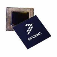
MPC8245LZU333D Freescale Semiconductor, MPC8245LZU333D Datasheet - Page 26

MPC8245LZU333D
Manufacturer Part Number
MPC8245LZU333D
Description
IC MPU 32BIT 333MHZ 352-TBGA
Manufacturer
Freescale Semiconductor
Series
PowerQUICC IIr
Specifications of MPC8245LZU333D
Processor Type
MPC82xx PowerQUICC II 32-bit
Speed
333MHz
Voltage
2V
Mounting Type
Surface Mount
Package / Case
352-TBGA
Core Size
32 Bit
Program Memory Size
32KB
Cpu Speed
333MHz
Embedded Interface Type
I2C
Digital Ic Case Style
TBGA
No. Of Pins
352
Supply Voltage Range
1.9V To 2.2V
Rohs Compliant
No
Family Name
MPC82XX
Device Core
PowerPC
Device Core Size
64b
Frequency (max)
333MHz
Instruction Set Architecture
RISC
Supply Voltage 1 (typ)
2/2.1/3.3V
Operating Supply Voltage (max)
2.2/3.465V
Operating Supply Voltage (min)
1.9/3.135V
Operating Temp Range
0C to 105C
Operating Temperature Classification
Commercial
Mounting
Surface Mount
Pin Count
352
Package Type
TBGA
Lead Free Status / RoHS Status
Contains lead / RoHS non-compliant
Features
-
Lead Free Status / Rohs Status
Not Compliant
Available stocks
Company
Part Number
Manufacturer
Quantity
Price
Company:
Part Number:
MPC8245LZU333D
Manufacturer:
FREE
Quantity:
12
Company:
Part Number:
MPC8245LZU333D
Manufacturer:
MOTOROLA
Quantity:
648
Company:
Part Number:
MPC8245LZU333D
Manufacturer:
Freescale Semiconductor
Quantity:
10 000
Part Number:
MPC8245LZU333D
Manufacturer:
MOTOROLA/摩托罗拉
Quantity:
20 000
Electrical and Thermal Characteristics
4.6.2
Table 13
26
At recommended operating conditions with OV
All values refer to V
SCL clock frequency
Low period of the SCL clock
High period of the SCL clock
Setup time for a repeated START condition
Hold time (repeated) START condition (after this period, the first
clock pulse is generated)
Data setup time
Data input hold time:
Data output delay time:
Set-up time for STOP condition
Bus free time between a STOP and START condition
Noise margin at the LOW level for each connected device (including
hysteresis)
Pulse width of spikes which must be suppressed by
the input filter
Input current each I/O pin (input voltage is between
0.1 × OV
Capacitance for each I/O pin
Notes:
1. Output voltage (open drain or open collector) condition = 3 mA sink current.
2. Refer to the MPC8245 Integrated Processor Reference Manual for information on the digital filter used.
3. I/O pins obstruct the SDA and SCL lines if the OV
DD
provides the AC timing parameters for the I
and 0.9 × OV
I
2
C AC Electrical Specifications
IH
(min) and V
DD
MPC8245 Integrated Processor Hardware Specifications, Rev. 10
Parameter
(max)
IL
(max) levels (see
Table 12. I
Table 13. I
CBUS compatible masters
DD
of 3.3 V ± 5%.
Table
2
2
C DC Electrical Characteristics
C AC Electrical Specifications
I
2
DD
12).
C bus devices
is switched off.
t
I2KHKL
C
I
I
I
2
C interfaces.
Symbol
t
t
t
t
I2SVKH
I2DVKH
t
I2SXKL
t
t
I2PVKH
t
t
I2OVKL
I2KHDX
I2DXKL
I2CH
I2CL
V
f
I2C
–10
NL
—
0
4
4
4
4
4
1
0.1 × OV
Min
100
1.3
0.6
0.6
0.6
0
0.6
1.3
—
—
0
2
50
10
10
DD
Freescale Semiconductor
Max
0.9
400
—
—
—
—
—
—
—
—
—
—
μA
ns
pF
3
Unit
kHz
2
3
μs
μs
μs
μs
ns
μs
μs
μs
V


