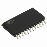
CY7C63743-SXC Cypress Semiconductor Corp, CY7C63743-SXC Datasheet - Page 33

CY7C63743-SXC
Manufacturer Part Number
CY7C63743-SXC
Description
IC MCU 8K USB/PS2 LS 24SOIC
Manufacturer
Cypress Semiconductor Corp
Series
enCoRe™r
Specifications of CY7C63743-SXC
Applications
USB Microcontroller
Core Processor
M8B
Program Memory Type
OTP (8 kB)
Controller Series
CY7C637xx
Ram Size
256 x 8
Interface
PS2, USB
Number Of I /o
16
Voltage - Supply
4 V ~ 5.5 V
Operating Temperature
0°C ~ 70°C
Mounting Type
Surface Mount
Package / Case
24-SOIC (7.5mm Width)
Lead Free Status / RoHS Status
Lead free / RoHS Compliant
Other names
428-1622
Available stocks
Company
Part Number
Manufacturer
Quantity
Price
Part Number:
CY7C63743-SXC
Manufacturer:
CYPRESS/赛普拉斯
Quantity:
20 000
Mode Column:
The ’Mode’ column contains the mnemonic names given to the
modes of the endpoint. The mode of the endpoint is deter-
mined by the four-bit binaries in the ’Encoding’ column as
discussed below. The Status IN and Status OUT modes
represent the status IN or OUT stage of the control transfer.
Encoding Column:
The contents of the ’Encoding’ column represent the Mode Bits
[3:0] of the Endpoint Mode Registers (Figure 14-2 and
Figure 14-3). The endpoint modes determine how the SIE
responds to different tokens that the host sends to the
endpoints. For example, if the Mode Bits [3:0] of the Endpoint
0 Mode Register (Figure 14-2) are set to ’0001’, which is NAK
IN/OUT mode as shown in Table 22-1 above, the SIE of the
part will send an ACK handshake in response to SETUP
tokens and NAK any IN or OUT tokens. For more information
on the functionality of the Serial Interface Engine (SIE), see
Section 13.0.
SETUP, IN, and OUT Columns:
Depending on the mode specified in the ’Encoding’ column,
the ’SETUP’, ’IN’, and ’OUT’ columns contain the device SIE’s
responses when the endpoint receives SETUP, IN, and OUT
tokens respectively.
A ’Check’ in the Out column means that upon receiving an
OUT token the SIE checks to see whether the OUT is of zero
length and has a Data Toggle (Data1/0) of 1. If these condi-
tions are true, the SIE responds with an ACK. If any of the
above conditions is not met, the SIE will respond with either a
STALL or Ignore. Table 22-3 gives a detailed analysis of all
possible cases.
A ’TX Count’ entry in the IN column means that the SIE will
transmit the number of bytes specified in the Byte Count Bit
Table 22-2. Decode table for Table 22-3: “Details of Modes for Differing Traffic Conditions”
Document #: 38-08022 Rev. *B
3
Legend:
Endpoint Mode
Encoding
2
(SETUP, IN,OUT)
Received Token
1
0
Token
count
The number of received bytes
UC: unchanged
x: don’t care
available for Control endpoint only
Properties of incoming
packet
buffer
The quality status of the DMA buffer
The validity of the received data
dval
FOR
FOR
DTOG
Data 0/1 (Bit 7, Figure 14-4)
TX: transmit
RX: receive
Changes to the internal register made by the SIE as a result of
DVAL
Data Valid (Bit 6, Figure 14-4)
COUNT
Bit[3:0], Figure 14-4
[3:0] of the Endpoint Count Register (Figure 14-4) in response
to any IN token.
A ’TX 0 Byte’ entry in the IN column means that the SIE will
transmit a zero byte packet in response to any IN sent to the
endpoint. Sending a 0 byte packet is to complete the status
stage of a control transfer.
An ’Ignore’ means that the device sends no handshake tokens.
An ’Accept’ means that the SIE will respond with an ACK to a
valid SETUP transaction.
Comments Column:
Some Mode Bits are automatically changed by the SIE in
response to many USB transactions. For example, if the Mode
Bits [3:0] are set to ’1111’ which is ACK IN-Status OUT mode
as shown in Table 22-1, the SIE will change the endpoint Mode
Bits [3:0] to NAK IN-Status OUT mode (1110) after ACKing a
valid status stage OUT token. The firmware needs to update
the mode for the SIE to respond appropriately. See Table 22-1
for more details on what modes will be changed by the SIE.
Any SETUP packet to an enabled endpoint with mode set to
accept SETUPs will be changed by the SIE to 0001 (NAKing).
Any mode set to accept a SETUP will send an ACK handshake
to a valid SETUP token.
A disabled endpoint will remain disabled until changed by
firmware, and all endpoints reset to the Disabled mode (0000).
Firmware normally enables the endpoint mode after a SetCon-
figuration request.
The control endpoint has three status bits for identifying the
token type received (SETUP, IN, or OUT), but the endpoint
must be placed in the correct mode to function as such.
Non-control endpoints should not be placed into modes that
accept SETUPs.
the incoming token
Setup
TX0: transmit 0-length packet
(Bit[7:5], Figure 14-2)
PID Status Bits
In
Out
ACK
Acknowledge transaction completed
(Bit4,Figure 14-2/3)
End Point
Mode
3
Endpoint Mode changed
by the SIE.
2 1 0 Response
CY7C63722
CY7C63723
CY7C63743
SIE’s Response
Page 33 of 49
Interrupt?
Int


