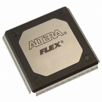
EPF10K100ARI240-3 Altera, EPF10K100ARI240-3 Datasheet - Page 16

EPF10K100ARI240-3
Manufacturer Part Number
EPF10K100ARI240-3
Description
IC FLEX 10KA FPGA 100K 240-RQFP
Manufacturer
Altera
Series
FLEX-10K®r
Datasheet
1.EPF10K10ATC100-3.pdf
(128 pages)
Specifications of EPF10K100ARI240-3
Number Of Logic Elements/cells
4992
Number Of Labs/clbs
624
Total Ram Bits
24576
Number Of I /o
189
Number Of Gates
158000
Voltage - Supply
3 V ~ 3.6 V
Mounting Type
Surface Mount
Operating Temperature
-40°C ~ 100°C
Package / Case
240-RQFP
Family Name
FLEX 10KA
Number Of Usable Gates
100000
Number Of Logic Blocks/elements
4992
# Registers
1218
# I/os (max)
189
Frequency (max)
125MHz
Process Technology
CMOS
Operating Supply Voltage (typ)
3.3V
Logic Cells
4992
Ram Bits
24567
Device System Gates
158000
Operating Supply Voltage (min)
3V
Operating Supply Voltage (max)
3.6V
Operating Temp Range
-40C to 85C
Operating Temperature Classification
Industrial
Mounting
Surface Mount
Pin Count
240
Package Type
RQFP
Lead Free Status / RoHS Status
Contains lead / RoHS non-compliant
Other names
544-1251
Available stocks
Company
Part Number
Manufacturer
Quantity
Price
Company:
Part Number:
EPF10K100ARI240-3
Manufacturer:
HYNIX
Quantity:
1
Company:
Part Number:
EPF10K100ARI240-3
Manufacturer:
ALTERA
Quantity:
3 000
Company:
Part Number:
EPF10K100ARI240-3N
Manufacturer:
ALTERA
Quantity:
5 510
Company:
Part Number:
EPF10K100ARI240-3N
Manufacturer:
ALTERA
Quantity:
1
16
FLEX 10K Embedded Programmable Logic Device Family Data Sheet
Figure 7
with the carry chain. One portion of the LUT generates the sum of two bits
using the input signals and the carry-in signal; the sum is routed to the
output of the LE. The register can either be bypassed for simple adders or
be used for an accumulator function. The carry chain logic generates the
carry-out signal, which is routed directly to the carry-in signal of the next-
higher-order bit. The final carry-out signal is routed to an LE, where it can
be used as a general-purpose signal.
Figure 7. Carry Chain Operation (n-bit Full Adder)
an
bn
a1
b1
a2
b2
Carry-In
shows how an n-bit full adder can be implemented in n + 1 LEs
Carry Chain
Carry Chain
Carry Chain
Carry Chain
LUT
LUT
LUT
LUT
Register
Register
Register
Register
LEn + 1
LEn
LE1
LE2
Altera Corporation
sn
Carry-Out
s1
s2


