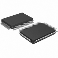
SAA7706H/N210,518 NXP Semiconductors, SAA7706H/N210,518 Datasheet - Page 13

SAA7706H/N210,518
Manufacturer Part Number
SAA7706H/N210,518
Description
IC CAR RADIO DSP 80-QFP
Manufacturer
NXP Semiconductors
Type
Car Signal Processorr
Datasheet
1.SAA7706HN210S518.pdf
(52 pages)
Specifications of SAA7706H/N210,518
Interface
I²C, I²S, LSB, SPDIF
Voltage - I/o
3.30V
Voltage - Core
3.30V
Operating Temperature
-40°C ~ 85°C
Mounting Type
Surface Mount
Package / Case
80-QFP
Lead Free Status / RoHS Status
Lead free / RoHS Compliant
Clock Rate
-
Non-volatile Memory
-
On-chip Ram
-
Other names
935270285518
SAA7706H/N210-T
SAA7706H/N210-T
SAA7706H/N210-T
SAA7706H/N210-T
Available stocks
Company
Part Number
Manufacturer
Quantity
Price
Company:
Part Number:
SAA7706H/N210,518
Manufacturer:
NXP Semiconductors
Quantity:
10 000
Philips Semiconductors
8.1.1
A high common mode rejection ratio can be created by the
use of the ground return pin. Pin CD_(L)_GND can be
used in the case that the left and right channel have one
ground return line. CD_(L)_GND and CD_R_GND can be
used for separated left and right ground return lines. The
ground return lines can be connected via the switch
GNDC1/2 and GNDRC1/2 (see Fig.4) to the plus input of
the second operational amplifier in the signal path. The
signal of which a high common mode rejection ratio is
required has a signal and a common signal as input. The
common signal is connected to the CD_(L)_GND and/or
CD_R_GND input. The actual input can be selected with
audio input control AIC1/2(1:0).
2001 Mar 05
handbook, full pagewidth
Car radio Digital Signal Processor (DSP)
CD-player
T
AIC
analog
from
HE REALIZATION OF COMMON MODE INPUT WITH
Fig.4 Example of the use of common mode analog input in combination with input resistor tap.
GROUND
GROUND
RIGHT
LEFT
RIGHT
LEFT
82 k
82 k
1 M
100 k
1 M
100 k
CD_(L)_GND
off-chip
CD_R_GND
VREFAD
CD_R
CD_L
72
77
78
14
70
on-chip
00
01
10
11
00
01
10
11
13
MUX
MUX
MIDREF
In Fig.4 the CD input is selected. In this situation both
signal lines going to S1/2 in front of the ADC will contain
the common mode signal. The ADC itself will suppress this
common mode signal with a high rejection ratio. The inputs
CD_L and CD_R in this example are connected via an
external resistor tap of 82 k and 100 k to be able to
handle larger input signals. The 100 k resistors are
needed to provide a DC biasing of the operational
amplifiers OA1 and OA2. The 1 M resistor provides
DC biasing of OA3 and OA4. If no external resistor tap is
needed the resistors of 100 k and 1 M still have to
provide DC biasing. Only the 82 k resistor can be
removed. The impedance level in combination with
parasitic capacitance at input CD_L or CD_R determines
for a great deal the achievable common rejection ratio.
G1
G0
10 k
10 k
OA1
OA2
10 k
10 k
10 k
10 k
OA3
OA4
MGT460
Product specification
to MUX S1/2
to MUX S1/2
AIC1/2(1:0)
GNDC1/2
GNDRC1/2
SAA7706H


