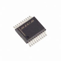
MAX1112CAP+ Maxim Integrated Products, MAX1112CAP+ Datasheet - Page 17

MAX1112CAP+
Manufacturer Part Number
MAX1112CAP+
Description
IC ADC 8-BIT 50KSPS 20-SSOP
Manufacturer
Maxim Integrated Products
Datasheet
1.MAX1113CEE.pdf
(20 pages)
Specifications of MAX1112CAP+
Number Of Bits
8
Sampling Rate (per Second)
50k
Data Interface
MICROWIRE™, QSPI™, Serial, SPI™
Number Of Converters
1
Power Dissipation (max)
680µW
Voltage Supply Source
Single Supply
Operating Temperature
0°C ~ 70°C
Mounting Type
Surface Mount
Package / Case
20-SSOP
Number Of Adc Inputs
8
Architecture
SAR
Conversion Rate
50 KSPs
Resolution
8 bit
Input Type
Differential
Interface Type
4-Wire (SPI, QSPI, MICROWIRE)
Voltage Reference
Internal 4.096 V or External
Supply Voltage (max)
5.5 V
Supply Voltage (min)
4.5 V
Maximum Power Dissipation
640 mW
Maximum Operating Temperature
+ 70 C
Mounting Style
SMD/SMT
Minimum Operating Temperature
0 C
Lead Free Status / RoHS Status
Lead free / RoHS Compliant
To use the MAX1112/MAX1113 with the internal refer-
ence, connect REFIN to REFOUT. The full-scale range
of the MAX1112/MAX1113 with the internal reference is
typically 4.096V with unipolar inputs, and ±2.048V with
bipolar inputs. The internal reference should be
bypassed to AGND with a 1µF capacitor placed as
close to the REFIN pin as possible.
Figure 14a. Power-Down Modes, External Clock Timing Diagram
Figure 14b. Power-Down Modes, Internal Clock Timing Diagram
CLOCK
MODE
MODE
SSTRB
MODE
SHDN
DOUT
DOUT
DIN
DIN
INTERNAL
S X X X X X 1 1
S X X X X X 1 0
______________________________________________________________________________________
SETS EXTERNAL
CLOCK MODE
SETS INTERNAL
CLOCK MODE
POWERED UP
CONVERSION
DATA VALID
Internal Reference
+5V, Low-Power, Multi-Channel,
POWERED UP
EXTERNAL
S
DATA VALID
X
X
X
X
X
INTERNAL CLOCK MODE
0 1
SETS POWER-
DOWN MODE
S
DATA VALID
X
X
Table 4 shows the full-scale voltage ranges for unipolar
and bipolar modes. Figure 15 depicts the nominal,
unipolar I/O transfer function, and Figure 16 shows the
bipolar I/O transfer function when using a 4.096V refer-
ence. Code transitions occur at integer LSB values.
Output coding is binary, with 1LSB = 16mV
(4.096V/256) for unipolar operation and 1LSB = 16mV
[(4.096V/2 - -4.096V/2)/256] for bipolar operation.
X
X
X
0 0
SETS POWER-DOWN MODE
CONVERSION
POWER-
DOWN
SETS EXTERNAL
CLOCK MODE
Serial 8-Bit ADCs
S
X X X X X
POWERED UP
1 1
DATA VALID
POWER-DOWN
Transfer Function
EXTERNAL
POWER-
INVALID
DATA
DOWN
S
POWERED
POWERED
UP
UP
17


