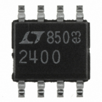
LTC2400CS8#PBF Linear Technology, LTC2400CS8#PBF Datasheet - Page 28

LTC2400CS8#PBF
Manufacturer Part Number
LTC2400CS8#PBF
Description
IC A/D CONV 24BIT MICRPWR 8-SOIC
Manufacturer
Linear Technology
Datasheet
1.LTC2400CS8PBF.pdf
(40 pages)
Specifications of LTC2400CS8#PBF
Number Of Bits
24
Sampling Rate (per Second)
7.5
Data Interface
MICROWIRE™, Serial, SPI™
Number Of Converters
1
Power Dissipation (max)
1mW
Voltage Supply Source
Single Supply
Operating Temperature
0°C ~ 70°C
Mounting Type
Surface Mount
Package / Case
8-SOIC (0.154", 3.90mm Width)
Lead Free Status / RoHS Status
Lead free / RoHS Compliant
Available stocks
Company
Part Number
Manufacturer
Quantity
Price
LTC2400
TYPICAL APPLICATIONS
LTC2400 High Accuracy Differential to Single-Ended
Converter for 5V Supplies
The circuit in Figure 30 is ideal for low level differential
signals in applications that have a 5V supply and need
high accuracy without calibration. The circuit combines an
LTC1043 and LTC1050 as a differential to single-ended
amplifier that has an input common mode range that
includes the power supplies. Resistors R1 and R2 set the
LTC1050’s gain at 101.
The circuit schematic shows an optional resistor R
resistor can be placed in series with the LTC2400’s input
to limit current if the input goes below – 300mV. The
resistor does not degrade the converter’s performance as
long as any capacitance, stray or otherwise, connected
between the LTC2400’s input and ground is less than
100pF. Higher capacitance will increase offset and full-
scale errors (see Input Current section).
The circuit achieves a nonlinearity of 1ppm, input re-
ferred noise of 0.05 V
bits resolution for a full-scale input of 40mV, and an overall
accuracy of 20 bits when using an LTC1236-5 precision
5V reference.
28
Figure 29. Simple Rail-to-Rail Circuit Converts Differential Signals to Single-Ended Signals
RMS
(averaging 64 samples), 19.6
DIFFERENTIAL
0.1 F
MAGNITUDE
0.01 F
LARGE
INPUT
C1
U
– 5V
13
16
17
7
LTC1043
5V
11
12
1/2
4
0.1 F
C
1 F
EXT
S
S
. This
14
8
3
C
1 F
V
H
2
REFIN
V
Multiple Inputs
The simple circuit shown in Figure 31 takes advantage of
the LTC2400’s single conversion settling. The LTC1391
serially programmed multiplexer allows accurate conver-
sions on each of its eight channels without introducing any
offset, gain or linearity errors with its input signal between
0V and V
the LTC2400’s input is less than 1000pF. A small 2ppm
(typ) error occurs when an active input channel’s signal
voltage reaches –300mV (typ). If the excursion below
ground is above – 200mV (typ), the error is less than the
LTC2400’s 0.3ppm
input signal’s magnitude can go above the 5V supply with
no linearity degradation or increased noise. Figure 31’s
circuit can tolerate overdrive on the unselected channel
without conversion degradation as long as the overdrive is
less than 250mV above the supply voltage or 250mV
below ground. The linearity performance is similar to that
shown in the Typical Performance Characteristics section.
Errors caused by channel-to-channel crosstalk are less
than the LTC2400’s typical input noise. This remains the
case for a frequency range of 1Hz to 153.6kHz (the
LTC2400’s internal clock frequency or 10f
frequency reaches 1.536MHz (4V
cally doubles and the linearity is degraded by 30ppm (typ).
IN
V
REF
GND
V
5V
CC
LTC2400
1
4
0.1 F
REF
F
O
8
, as long as the total capacitance connected to
SDO
SCK
CS
5
6
7
RMS
CHIP SELECT
SERIAL
SERIAL
noise. On the topside, the selected
2400 F29
P-P
), the RMS noise typi-
S
). When the


