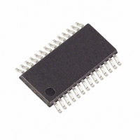
MAXQ3181-RAN+ Maxim Integrated Products, MAXQ3181-RAN+ Datasheet - Page 58

MAXQ3181-RAN+
Manufacturer Part Number
MAXQ3181-RAN+
Description
IC AFE POLYPHASE LO-PWR 28-TSSOP
Manufacturer
Maxim Integrated Products
Datasheet
1.MAXQ3181-RAN.pdf
(84 pages)
Specifications of MAXQ3181-RAN+
Number Of Channels
8
Power (watts)
35mW
Voltage - Supply, Analog
3.3V
Voltage - Supply, Digital
3.3V
Package / Case
28-TSSOP
Lead Free Status / RoHS Status
Lead free / RoHS Compliant
Number Of Bits
-
Low-Power, Active Energy, Polyphase AFE
The conversions from meter units to physical units are
illustrated with the simplified input circuits in Figures 13
and 14. The voltage input circuit is a voltage-divider.
Current input is through a current transfer with turn ratio
of 2000:1.
The voltage transducer ratio (V
545, V
The current transducer ratio (I
2000/(2 x 10) =100 (A/V), I
The input circuits should be designed to avoid getting
too close to the ADC input full sale at the specified
maximum ratings. So for the above circuits, we would
specify the maximum input current = 70A (RMS) and
maximum voltage = 390V (RMS), to ensure that peak of
sinusoudal waveform never exceeds I
Use the default ADC timing t
lowing meter unit to physical unit conversion coeffi-
cients (these coefficients are not part of the MAXQ3181
registers):
For example, if we get 0x07654AF0 from reading
0x1CC register (phase A current RMS), the current
value it represents is
For some low-end host microcontrollers, doing the
above math multiplication above could be difficult. For
this reason, the MAXQ3181 provides conversions for
some commonly needed parameters through the
VOLT_CC, AMP_CC, PWR_CC, and ENR_CC registers.
For example, if you want to display current in the reso-
lution of 1mA, without having to use a multiplication
Figure 13. Sample Voltage Input Circuit
58
______________________________________________________________________________________
MU_ENR = V
FS
MU_PWR = V
VA (AC)
= 558.1V.
0x07654AF0 x MU_AMP = 47.33 (A)
MU_VOLT = V
MU_AMP = I
544kΩ
FS
R1
Units Conversion Examples
x I
FS
FS
x I
FS
FS
x t
FS
/2
FS
/2
1kΩ
FR
FR
24
R2
24
/2
= 102.4A.
32
/2
= 6.1E-6 (A)
= 320μs, we get the fol-
= 33.3E-6 (V)
TR
TR
16
= 13.3E-6 (W)
) = CT_N/(2 x R) =
) = (R1 + R2)/R2 =
VOP
VN
= 77.5E-9 (Wh)
MAXQ3181
FS
or V
FS
.
operation to convert from the meter unit value
0x07654AF0, you would set AMP_CC to 0x0190, and
read from virtual register 0x831 (phase A RMS current).
The output would be 0xB8E45170. Dropping the lower
2 bytes (right shifting 16 bits) gives 0xB8E4, or 47332
decimal (47332mA).
AMP_CC is computed as follows:
Calibration ensures that the recorded voltage, current,
energy, and power are in accordance with the design
criteria. Before creating a calibration regimen, establish
the fundamental units of the meter: the full-scale volt-
age and current. Then adjust the gain registers using
calculated calibration constants to produce the expect-
ed reading in the raw current, voltage, energy, and
power factor registers.
The calibration constants should be stored in non-
volatile memory by the host microcontroller. Upon any
reset or loss of power, the host microcontroller must
reload the MAXQ3181 with the constants.
Calibration always follows a set of fundamental steps:
• Apply a known signal (voltage/current/power) to the
• Read the meter.
• Calculate the correction factor based on the differ-
• Write the correction factor to the appropriate register.
Figure 14. Sample Current Input Circuit
AMP_CC = (I
AMP_CC = (102.4/2
meter.
ence between the applied signal level and the meter
reading.
IA (AC)
FS
AMP_LSB = 0.001/2
/2
24
)/AMP_LSB = MU_AMP/AMP_LSB
Calibration Procedure
I
24
FS
)/(0.001/2
10Ω
10Ω
= 102.4A
R
R
Calibration Overview
I0P
VCOMM
I0N
16
MAXQ3181
16
) = 400d = 0x0190
(A)


