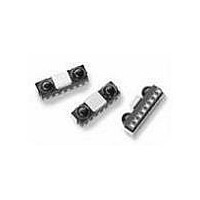
HSDL-3220-021 Lite-On Electronics, HSDL-3220-021 Datasheet - Page 3

HSDL-3220-021
Manufacturer Part Number
HSDL-3220-021
Description
Infrared Transceivers IR Transceiver
Manufacturer
Lite-On Electronics
Datasheet
1.HSDL-3220-021.pdf
(18 pages)
Specifications of HSDL-3220-021
Wavelength
875 nm, 880 nm
Continual Data Transmission
4 Mbit/s
Transmission Distance
50 cm
Radiant Intensity
45 mW/sr
Half Intensity Angle Degrees
30 deg to 60 deg
Pulse Width
4 us, 1.6 us
Maximum Rise Time
60 ns, 600 ns
Maximum Fall Time
60 ns, 600 ns
Led Supply Voltage
0 V to 6.5 V
Maximum Forward Current
50 mA
Operating Voltage
2.7 V to 3.6 V
Maximum Operating Temperature
+ 70 C
Minimum Operating Temperature
- 25 C
Dimensions
8 mm x 3 mm x 2.5 mm
Data Rate
4Mbs (FIR)
Idle Current, Typ @ 25° C
1.8 mA
Link Range, Low Power
1m
Operating Temperature
-25°C ~ 70°C
Orientation
Side View
Shutdown
*
Size
8mm x 3mm x 2.5mm
Standards
IrPHY 1.4
Supply Voltage
2.7 V ~ 3.6 V
Lead Free Status / RoHS Status
Compliant
Lead Free Status / RoHS Status
Lead free / RoHS Compliant, Compliant
Bandwidth Selection Timing
The transceiver is in default SIR/ MIR mode when pow-
ered on. User needs to apply the following program-
ming sequence to both the SD and TXD inputs to en-
able the transceiver to operate at FIR mode.
Figure 3. Bandwidth selection timing at SIR/MIR mode.
Setting the transceiver to SIR/MIR Mode (9.6 kbit/s to
1.152 Mbit/s)
1. Set SD/Mode input to logic HIGH
2. TXD input should remain at logic LOW
3. After waiting for t
4. Ensure that TXD input remains low for t
5. SD input pulse width for mode selection should be >
Transceiver I/O Truth Table
TXD
High
Low
Low
Don’t Care
Notes:
12. In-band IrDA signals and data rates ≤ 4.0 Mbit/s
13. RXD logic low is a pulsed response. The condition is maintained for a duration dependent on pattern and
3
Figure 3. Bandwidth selection timing at SIR/MIR mode.
SD/MODE
the HIGH to LOW negative edge transition will deter-
mine the receiver bandwidth
receiver is now in SIR/MIR mode
50 ns.
strength of the incident intensity.
CAUTIONS: The BiCMOS inherent to the design of this component increases the component’s susceptibility to
damage from electrostatic discharge (ESD). It is advised that normal static precautions be taken in handling and
assembly of this component to prevent damage and/or degradation which may be induced by ESD.
TXD
Inputs
Light Input to Receiver
Don’t Care
High
Low
Don’t Care
50%
S
≥ 25 ns, set SD/Mode to logic LOW,
t
S
50%
t
H
H
50%
≥ 100 ns, the
V
V
IH
IL
SD
Low
Low
Low
High
V
IL
Figure 4. Bandwidth selection timing at FIR mode.
Setting the transceiver to FIR (4.0 Mbit/s) Mode
1. Set SD/Mode input to logic HIGH
2. After SD/Mode input remains HIGH at > 25 ns, set TXD
3. Then set SD/Mode to logic LOW, the HIGH to LOW
4. After waiting for t
5. SD input pulse width mode selection should be >
SD/MODE
Figure 4. Bandwidth selection timing at FIR mode.
input to logic HIGH, wait t
rising edge till 50% of SD falling edge)
negative edge transition will determine the receiver
bandwidth
LOW
50 ns.
TXD
Outputs
LED
On
Off
Off
Off
50%
H
≥ 100 ns, set the TXD input to logic
RXD
Not Valid
Low
High
High
t
S
S
≥ 25 ns (from 50% of TXD
50%
t
H
50%
Note
12,13
V
V
IH
IL
V
V
IH
IL


