HSDL-3220-021 Lite-On Electronics, HSDL-3220-021 Datasheet
HSDL-3220-021
Specifications of HSDL-3220-021


Related parts for HSDL-3220-021


HSDL-3220-021 Summary of contents
Page 1
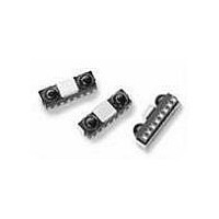
... Infrared Transceiver Data Sheet Description The HSDL-3220 is a new generation low profile high speed infrared transceiver module that provides inter- face between logic and IR signals for through-air, serial, half-duplex IR data-link. The module is fully compliant to IrDA Physical Layer specification version 1.4 low power from 9 ...
Page 2
... HSDL-3220 infrared transceiver module. You can con- tact them through your local sales representatives for additional details. Order Information Part Number Packaging Type HSDL-3220-021 Tape and Reel I/O Pins Configuration Table Pin Symbol 1 LED A ...
Page 3
Bandwidth Selection Timing The transceiver is in default SIR/ MIR mode when pow- ered on. User needs to apply the following program- ming sequence to both the SD and TXD inputs to en- able the transceiver to operate at FIR ...
Page 4
Absolute Maximum Ratings For implementations where case to ambient thermal resistance is ≤50°C/W. Parameter S torage Temperature Operating Temperature LED Anode Voltage Supply Voltage Input Voltage: TXD, SD/Mode Output Voltage: RXD DC LED Transmit Current Average Transmit Current Recommended Operating ...
Page 5
Electrical and Optical Specifications Specifications (Min. and Max. values) hold over the recommended operating conditions unless otherwise noted. Unspecified test conditions may be anywhere in their operating range. All typical values (Typ.) are at 25°C, Vcc set to 3.0V and ...
Page 6
V OH 90% 50% 10 Figure 5. RxD output waveform. TXD LED t pw (MAX.) Figure 7. TxD “Stuck On” protection waveform. 120 100 0.10 0.15 0.20 0.25 I ...
Page 7
... HSDL-3220 Package Dimensions 7 ...
Page 8
... HSDL-3220 Tape and Reel Dimensions Unit: mm Ø1.5 POLARITY Pin 8: VLED Pin 1: GND 8.4 ± 0.1 0.4 ± 0.05 3.4 ± 0.1 2.8 ± 0.1 Empty Parts Mounted (40 mm min) LABEL Note: The carrier tape is compliant to the packaging materials standards for ESD sensitive device, EIA-541 8 4.0 ± ...
Page 9
... Moisture Proof Packaging All HSDL-3220 options are shipped in moisture proof package. Once opened, moisture absorption begins. This part is compliant to JEDEC Level 4. UNITS IN A SEALED MOISTURE-PROOF PACKAGE PACKAGE IS OPENED (UNSEALED) ENVIRONMENT LESS THAN 30°C, AND LESS THAN 60% RH YES PACKAGE IS NO BAKING ...
Page 10
... The ∆T/∆time rates are detailed in the above table. The temperatures are measured at the com- ponent to printed circuit board connections. In process zone P1, the PC board and HSDL-3220 cas- tellation pins are heated to a temperature of 160°C to activate the flux in the solder paste. The temperature ramp up rate, R1, is limited to 4° ...
Page 11
Appendix A: SMT Assembly Application Note Solder Pad, Mask and Metal Stencil Aperture STENCIL APERTURE SOLDER MASK Figure 12. Stencil and PCBA. Recommended Land Pattern C L 1.35 MOUNTING CENTER 0.10 1.75 0.60 0.475 1.425 UNIT: mm Figure 13. Stencil ...
Page 12
Recommended Metal Solder Stencil Aperture It is recommended that only a 0.152 mm (0.006 inches 0.127 mm (0.005 inches) thick stencil be used for solder paste printing. This is to ensure adequate printed solder paste volume and no ...
Page 13
Appendix B: PCB Layout Suggestion The following PCB layout guidelines should be followed to obtain a good PSRR and EM immunity resulting in good electrical performance. Things to note: 1. The ground plane should be continuous under the part, but ...
Page 14
... USER INTERFACE Figure 17. Mobile phone platform. 14 Interface to Recommended I/O chips The HSDL-3220’s TXD data input is buffered to allow for CMOS drive levels. No peaking circuit or capacitor is required. Data rate from 9.6 kbit 4.0 Mbit/s is available at the RXD pin. The block diagram below shows how the IR port fits into a mobile phone and PDA platform ...
Page 15
... ROM PCMCIA Controller RS232C Driver PDA Platform Figure 18. PDA platform. The link distance testing was done using typical HSDL- 3220 units with SMC’s FDC37C669 and FDC37N769 Super I/O controllers link distance was demonstrated for SIR and FIR speeds. 15 LCD Panel ...
Page 16
... The depth of the LED image inside the HSDL-3220 3.17 mm. ‘A’ is the required half angle for viewing. For IrDA compliance, the minimum is 15° and the maximum is 30° ...
Page 17
Module Depth (z) mm APERTURE WIDTH (X) vs. MODULE DEPTH MODULE DEPTH (Z) – mm Figure ...
Page 18
Shape of the Window From an optics standpoint, the window should be flat. This ensures that the window will not alter either the radiation pattern of the LED, or the receive pattern of the photodiode. If the window must be ...