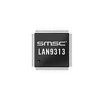
LAN9313-NZW SMSC, LAN9313-NZW Datasheet - Page 76

LAN9313-NZW
Manufacturer Part Number
LAN9313-NZW
Description
Ethernet ICs Three Port 10/100 Ethernet Switch
Manufacturer
SMSC
Type
Three Port Managed Ethernet Switchr
Datasheet
1.LAN9313-NZW.pdf
(399 pages)
Specifications of LAN9313-NZW
Ethernet Connection Type
10 Base-T, 100 Base-TX
Minimum Operating Temperature
0 C
Mounting Style
SMD/SMT
Product
Ethernet Switches
Number Of Transceivers
1
Standard Supported
802.3, 802.3u
Data Rate
10 Mbps, 100 Mbps
Supply Voltage (max)
3.6 V
Supply Voltage (min)
0 V
Supply Current (max)
155 mA, 270 mA
Maximum Operating Temperature
+ 70 C
Package / Case
TQFP-100
Lead Free Status / RoHS Status
Lead free / RoHS Compliant
Available stocks
Company
Part Number
Manufacturer
Quantity
Price
Company:
Part Number:
LAN9313-NZW
Manufacturer:
Microchip Technology
Quantity:
10 000
Part Number:
LAN9313-NZW
Manufacturer:
SMSC
Quantity:
20 000
- Current page: 76 of 399
- Download datasheet (5Mb)
Revision 1.7 (06-29-10)
6.4.7
6.4.8
Broadcast Throttle Level
Broadcast Storm Control
In addition to ingress rate limiting, the LAN9313/LAN9313i supports hardware broadcast storm control
on a per port basis. This feature is enabled via the
(SWE_BCST_THROT). The allowed rate per port is specified as the number of bytes multiplied by 64
allowed to be received every 1.72 mS interval. Packets that exceed this limit are dropped. Typical
values are listed in
of not limiting the rate.
In addition to the rate limit, the
specifies the maximum number of buffers that can be used by broadcasts, multicasts, and unknown
unicasts.
IPv4 IGMP Support
The LAN9313/LAN9313i provides Internet Group Management Protocol (IGMP) hardware support
using two mechanisms: IGMP monitoring and Multicast Pruning.
On ingress, if IGMP packet monitoring is enabled in the
Register
IGMP monitoring port (typically set to the port to which the host CPU is connected). IGMP packets are
identified as IPv4 packets with a protocol of 2. Both Ethernet and IEEE 802.3 frame formats are
supported as are VLAN tagged packets.
Once the IGMP packets are received by the host CPU, the host software can decide which port or
ports need to be members of the multicast group. This group is then added to the ALR table as detailed
in
IGMP packet if necessary.
Normally, packets are never transmitted back to the receiving port. For IGMP monitoring, this may
optionally be enabled via the
(SWE_GLOBAL_INGRSS_CFG). This function would be used if the monitoring port wished to
participate in the IGMP group without the need to perform special handling in the transmit portion of
the driver software.
Section 6.4.1.3, "Multicast Pruning," on page
252
168
134
(SWE_GLOBAL_INGRSS_CFG), IGMP multicast packets are trapped and redirected to the
67
34
17
8
4
3
2
1
Table
Table 6.4 Typical Broadcast Rate Settings
6.4. When a port is receiving at 10Mbps, any setting above 34 has the effect
Buffer Manager Broadcast Buffer Level Register (BM_BCST_LVL)
DATASHEET
Switch Engine Global Ingress Configuration Register
76
66. The host software should also forward the original
Switch Engine Broadcast Throttling Register
Switch Engine Global Ingress Configuration
Three Port 10/100 Managed Ethernet Switch with MII
Bandwidth
900 Kbps
600 Kbps
300 Kbps
2.4 Mbps
1.2 Mbps
75 Mbps
50 Mbps
40 Mbps
20 Mbps
10 Mbps
5 Mbps
SMSC LAN9313/LAN9313i
Datasheet
Related parts for LAN9313-NZW
Image
Part Number
Description
Manufacturer
Datasheet
Request
R

Part Number:
Description:
Ethernet ICs Three Port 10/100 Ethernet Switch
Manufacturer:
SMSC
Datasheet:

Part Number:
Description:
FAST ETHERNET PHYSICAL LAYER DEVICE
Manufacturer:
SMSC Corporation
Datasheet:

Part Number:
Description:
357-036-542-201 CARDEDGE 36POS DL .156 BLK LOPRO
Manufacturer:
SMSC Corporation
Datasheet:

Part Number:
Description:
357-036-542-201 CARDEDGE 36POS DL .156 BLK LOPRO
Manufacturer:
SMSC Corporation
Datasheet:

Part Number:
Description:
357-036-542-201 CARDEDGE 36POS DL .156 BLK LOPRO
Manufacturer:
SMSC Corporation
Datasheet:

Part Number:
Description:
4-PORT USB2.0 HUB CONTROLLER
Manufacturer:
SMSC Corporation
Datasheet:

Part Number:
Description:
Manufacturer:
SMSC Corporation
Datasheet:

Part Number:
Description:
Manufacturer:
SMSC Corporation
Datasheet:

Part Number:
Description:
FDC37C672ENHANCED SUPER I/O CONTROLLER WITH FAST IR
Manufacturer:
SMSC Corporation
Datasheet:

Part Number:
Description:
COM90C66LJPARCNET Controller/Transceiver with AT Interface and On-Chip RAM
Manufacturer:
SMSC Corporation
Datasheet:

Part Number:
Description:
Manufacturer:
SMSC Corporation
Datasheet:

Part Number:
Description:
Manufacturer:
SMSC Corporation
Datasheet:

Part Number:
Description:
Manufacturer:
SMSC Corporation
Datasheet:

Part Number:
Description:
Manufacturer:
SMSC Corporation
Datasheet:


