BFG198 T/R NXP Semiconductors, BFG198 T/R Datasheet
BFG198 T/R
Specifications of BFG198 T/R


Related parts for BFG198 T/R


BFG198 T/R Summary of contents
Page 1
DATA SHEET BFG198 NPN 8 GHz wideband transistor Product specification DISCRETE SEMICONDUCTORS 1995 Sep 12 ...
Page 2
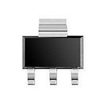
... NXP Semiconductors NPN 8 GHz wideband transistor DESCRIPTION NPN planar epitaxial transistor in a plastic SOT223 envelope, intended for wideband amplifier applications. The device features a high gain and excellent output voltage capabilities. QUICK REFERENCE DATA SYMBOL PARAMETER V collector-base voltage CBO V collector-emitter voltage CEO ...
Page 3
... NXP Semiconductors NPN 8 GHz wideband transistor THERMAL CHARACTERISTICS SYMBOL PARAMETER R thermal resistance from junction to soldering point th j-s Note the temperature at the soldering point of the collector tab. s CHARACTERISTICS = 25 C unless otherwise specified SYMBOL PARAMETER I collector cut-off current CBO h DC current gain FE C collector capacitance ...
Page 4
... NXP Semiconductors NPN 8 GHz wideband transistor handbook, full pagewidth input Ω Fig.2 Intermodulation distortion and second order intermodulation distortion test circuit. List of components (see test circuit) DESIGNATION DESCRIPTION C2 multilayer ceramic capacitor C1, C4, C6, C7 multilayer ceramic capacitor C3 multilayer ceramic capacitor C5 (note 1) multilayer ceramic capacitor ...
Page 5
... NXP Semiconductors NPN 8 GHz wideband transistor handbook, full pagewidth Ω 75 input handbook, full pagewidth handbook, full pagewidth Fig.3 Intermodulation distortion and second order intermodulation distortion printed-circuit board. 1995 Sep mounting screws M 2.5 (8x Ω output C8 MEA968 60 mm MEA966 60 mm MEA967 Product specification ...
Page 6
... NXP Semiconductors NPN 8 GHz wideband transistor 1.2 handbook, halfpage P tot (W) 1.0 0.8 0.6 0.4 0 100 Fig.4 Power derating curve. 1.2 handbook, halfpage C re (pF) 0.8 0 MHz Fig.6 Feedback capacitance as a function of collector-base voltage. 1995 Sep 12 MBB752 handbook, halfpage 150 200 MBB751 ...
Page 7
... NXP Semiconductors NPN 8 GHz wideband transistor 40 handbook, halfpage G UM (dB mA amb Fig.8 Maximum gain as a function of frequency. 45 handbook, halfpage d im (dB 700 mV amb f = 793.25 MHz. (p+q) Fig.10 Intermodulation distortion as a function of collector current. 1995 Sep 12 MBB753 handbook, halfpage (MHz) MBB266 handbook, halfpage ...
Page 8
... NXP Semiconductors NPN 8 GHz wideband transistor 35 handbook, halfpage d 2 (dB dBmV amb f = 810 MHz. (p+q) Fig.12 Second order intermodulation distortion as a function of collector current. 1995 Sep 12 MBB268 80 100 120 I (mA Product specification BFG198 ...
Page 9
... NXP Semiconductors NPN 8 GHz wideband transistor handbook, full pagewidth + j – mA amb Fig.13 Common emitter input reflection coefficient (S handbook, full pagewidth o 180 = 25 mA amb Fig.14 Common emitter forward transmission coefficient (S 1995 Sep GHz MHz 120 o 150 o 40 MHz 100 80 60 ...
Page 10
... NXP Semiconductors NPN 8 GHz wideband transistor handbook, full pagewidth o 180 = 25 mA amb Fig.15 Common emitter reverse transmission coefficient ( – mA amb Fig.16 Common emitter output reflection coefficient (S 1995 Sep 120 o 150 o 0.2 0.16 0.12 0.08 0.04 40 MHz 150 o 120 GHz 10 25 ...
Page 11
... NXP Semiconductors NPN 8 GHz wideband transistor PACKAGE OUTLINE Plastic surface-mounted package with increased heatsink; 4 leads DIMENSIONS (mm are the original dimensions) UNIT 1.8 0.10 0.80 3.1 mm 1.5 0.01 0.60 2.9 OUTLINE VERSION IEC SOT223 1995 Sep scale 0.32 6.7 3.7 7.3 4.6 2 ...
Page 12
... In no event shall NXP Semiconductors be liable for any indirect, incidental, punitive, special or consequential damages (including - without limitation - lost profits, lost savings, business interruption, costs related to the ...
Page 13
... NXP Semiconductors’ specifications such use shall be solely at customer’s own risk, and (c) customer fully indemnifies NXP Semiconductors for any liability, damages or failed product claims resulting from customer design and use of the product for automotive applications beyond NXP Semiconductors’ ...
Page 14
... Interface, Security and Digital Processing expertise Customer notification This data sheet was changed to reflect the new company name NXP Semiconductors, including new legal definitions and disclaimers. No changes were made to the technical content, except for package outline drawings which were updated to the latest version. ...