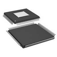
ADAU1445YSVZ-3A-RL Analog Devices Inc, ADAU1445YSVZ-3A-RL Datasheet - Page 12

ADAU1445YSVZ-3A-RL
Manufacturer Part Number
ADAU1445YSVZ-3A-RL
Description
175MHZ SigmaDSP,2x8 SRCs
Manufacturer
Analog Devices Inc
Series
SigmaDSP®r
Type
Audio Processorr
Specifications of ADAU1445YSVZ-3A-RL
Applications
Automotive Audio
Mounting Type
Surface Mount
Package / Case
100-TQFP Exposed Pad, 100-eTQFP, 100-HTQFP, 100-VQFP
Format
Fixed Point
Program Memory Size
Not RequiredKB
Operating Supply Voltage (typ)
1.8/3.3V
Operating Temp Range
-40C to 105C
Operating Temperature Classification
Industrial
Mounting
Surface Mount
Pin Count
100
Lead Free Status / RoHS Status
Lead free / RoHS Compliant
Lead Free Status / RoHS Status
Lead free / RoHS Compliant
Available stocks
Company
Part Number
Manufacturer
Quantity
Price
Company:
Part Number:
ADAU1445YSVZ-3A-RL
Manufacturer:
Analog Devices Inc
Quantity:
10 000
ADAU1445/ADAU1446
Pin No.
34
35
36
40
41
42
43
44
45
46
47
48
49
53
54
55
56
57
58
59
60
61
64
65
Mnemonic
MP6
MP5
MP4
VDRIVE
XTALO
XTALI
PLL_FILT
PVDD
PGND
SPDIFI
SPDIFO
AVDD
AGND
CLKOUT
RESET
MP3/ADC3
MP2/ADC2
MP1/ADC1
MP0/ADC0
PLL1
PLL0
SDATA_OUT8
BCLK11
LRCLK11
Type
D_IO
D_IO
D_IO
A_OUT
A_OUT
A_IN
A_OUT
PWR
PWR
D_IN
D_OUT
PWR
PWR
D_OUT
D_IN
D_IO,
A_IN
D_IO,
A_IN
D_IO,
A_IN
D_IO,
A_IN
D_IN
D_IN
D_OUT
D_IO
D_IO
1
Phase-Locked Loop Mode Select Pin 1.
Phase-Locked Loop Mode Select Pin 0.
Description
Multipurpose, General-Purpose Input/Output. When not used, this pin can be left disconnected.
Multipurpose, General-Purpose Input/Output. When not used, this pin can be left disconnected.
Multipurpose, General-Purpose Input/Output. When not used, this pin can be left disconnected.
Regulator Drive. Supplies the drive current for the 1.8 V regulator. The base of the voltage regulator’s
external PNP transistor is driven from VDRIVE.
Crystal Oscillator Output. A 100 Ω damping resistor should be connected between this pin and the
crystal. This output should not be used to directly drive a clock to another IC; the CLKOUT pin
exists for this purpose. If the crystal oscillator is not used, the XTALO pin can be left unconnected.
Crystal Oscillator Input. This pin provides the master clock for the ADAU1445/ADAU1446. If the
ADAU1445/ADAU1446 generate the master clock in the system, this pin should be connected to
the crystal oscillator circuit. If the ADAU1445/ADAU1446 are slaves to an external master clock, this
pin should be connected to the master clock signal generated by another IC.
Phase-Locked Loop Filter. Two capacitors and a resistor must be connected to this pin as shown in
Figure 11.
Phase-Locked Loop Supply. Provides the 3.3 V power supply for the PLL. This should be decoupled
to PGND with a100 nF capacitor.
Phase-Locked Loop Ground. Ground for the PLL supply. The AGND, DGND, and PGND pins can be
tied directly together in a common ground plane. PGND should be decoupled to PVDD with a
100 nF capacitor.
S/PDIF Input. Accepts digital audio data in the S/PDIF format. When not used, this pin can be left
disconnected.
S/PDIF Output. Outputs digital audio data in the S/PDIF format. When not used, this pin can be left
disconnected.
Analog Supply. 3.3 V analog supply for the auxiliary ADC. This pin should be decoupled to AGND
with a 100 nF capacitor.
Analog Ground. Ground for the analog supply. This pin should be decoupled to AVDD with a
100 nF capacitor.
Master Clock Output. Used to output a master clock to other ICs in the system. Set using the
CLKMODEx pins. When not used, this pin can be left disconnected.
Reset. Active-low reset input. Reset is triggered on a high-to-low edge and exited on a low-to-high
edge. For detailed information about initialization, see the Power-Up Sequence section. A reset
event sets all RAMs and registers to their default values.
Multipurpose, General-Purpose Input or Output/Auxiliary ADC Input 3. When not used, this pin can
be left disconnected.
Multipurpose, General-Purpose Input or Output/Auxiliary ADC Input 2. When not used, this pin can
be left disconnected.
Multipurpose, General-Purpose Input or Output/Auxiliary ADC Input 1. When not used, this pin can
be left disconnected.
Multipurpose, General-Purpose IO/Auxiliary ADC Input 0. When not used, this pin can be left
disconnected.
Serial Data Port 0 Output. When not used, this pin can be left disconnected.
Bit Clock, Output Clock Domain 2. This pin is bidirectional, with the direction depending on whether the
Output Clock Domain 2 is set up as a master or slave. When not used, this pin can be left disconnected.
Frame Clock, Output Clock Domain 2. This pin is bidirectional, with the direction depending on
whether the Output Clock Domain 2 is set up as a master or slave. When not used, this pin can be
left disconnected.
Rev. A | Page 12 of 92


