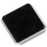
STM32F103ZGH6 STMicroelectronics, STM32F103ZGH6 Datasheet - Page 103

STM32F103ZGH6
Manufacturer Part Number
STM32F103ZGH6
Description
MCU 32BIT 1MB FLASH 144LQFP
Manufacturer
STMicroelectronics
Series
STM32r
Datasheet
1.STM32F103VGT6.pdf
(120 pages)
Specifications of STM32F103ZGH6
Core Processor
ARM® Cortex-M3™
Core Size
32-Bit
Speed
72MHz
Connectivity
CAN, I²C, IrDA, LIN, MMC, SPI, UART/USART, USB
Peripherals
DMA, I²S, LCD, POR, PWM, WDT
Number Of I /o
112
Program Memory Size
1MB (1M x 8)
Program Memory Type
FLASH
Ram Size
96K x 8
Voltage - Supply (vcc/vdd)
2 V ~ 3.6 V
Data Converters
A/D 21x12b; D/A 2x12b
Oscillator Type
Internal
Operating Temperature
-40°C ~ 85°C
Package / Case
*
Processor Series
STM32F101xG
Core
ARM Cortex M3
Data Bus Width
32 bit
Data Ram Size
80 KB
Interface Type
I2C, SPI, UART
Maximum Clock Frequency
36 MHz
Number Of Programmable I/os
112
Number Of Timers
15
Operating Supply Voltage
2 V to 3.6 V
Maximum Operating Temperature
+ 85 C
Mounting Style
SMD/SMT
Operating Temperature Range
- 40 C to + 105 C
Processor To Be Evaluated
STM32F103ZG
Supply Current (max)
28 mA
Lead Free Status / RoHS Status
Lead free / RoHS Compliant
Eeprom Size
-
Lead Free Status / Rohs Status
Details
Other names
497-11115
Available stocks
Company
Part Number
Manufacturer
Quantity
Price
Company:
Part Number:
STM32F103ZGH6
Manufacturer:
STMicroelectronics
Quantity:
135
Company:
Part Number:
STM32F103ZGH6
Manufacturer:
STMicroelectronics
Quantity:
10 000
Part Number:
STM32F103ZGH6
Manufacturer:
ST
Quantity:
20 000
STM32F103xF, STM32F103xG
Equation 1: R
The formula above
allowed for an error below 1/4 of LSB. Here N = 12 (from 12-bit resolution).
Table 60.
1. Guaranteed by design, not tested in production.
Table 61.
1. ADC DC accuracy values are measured after internal calibration.
2. ADC Accuracy vs. Negative Injection Current: Injecting negative current on any of the standard (non-
3. Preliminary values.
1.5
7.5
13.5
28.5
41.5
55.5
71.5
239.5
Symbol
R
robust) analog input pins should be avoided as this significantly reduces the accuracy of the conversion
being performed on another analog input. It is recommended to add a Schottky diode (pin to ground) to
standard analog pins which may potentially inject negative current.
Any positive injection current within the limits specified for I
affect the ADC accuracy.
EO
EG
ED
ET
EL
AIN
------------------------------------------------------------- - R
f
T
ADC
Total unadjusted error
Offset error
Gain error
Differential linearity error
Integral linearity error
s
R
(cycles)
ADC accuracy - limited test conditions
AIN
AIN
C
ADC
Parameter
max for f
max formula
(Equation
T
S
ln
2
ADC
N
1) is used to determine the maximum external impedance
+
Doc ID 16554 Rev 2
0.11
0.54
0.96
2.04
2.96
3.96
5.11
17.1
2
= 14 MHz
–
f
f
V
T
Measurements made after
ADC calibration
V
ADC
PCLK2
ADC
A
DDA
REF+
= 25 °C
= 14 MHz, R
(1)
= 3 V to 3.6 V
t
= V
S
= 56 MHz,
Test conditions
(µs)
DDA
INJ(PIN)
AIN
(1)(2)
and I
< 10 k,
INJ(PIN)
0.4
5.9
11.4
25.2
37.2
50
NA
NA
Electrical characteristics
in
±1.3
±0.5
±0.7
±0.8
Typ
±1
Section 5.3.14
R
AIN
max (k)
Max
±1.5
±1.5
±1.5
±1
±2
(3)
does not
103/120
Unit
LSB


