OKL-T/6-W5P-C Murata Power Solutions Inc, OKL-T/6-W5P-C Datasheet - Page 15
OKL-T/6-W5P-C
Manufacturer Part Number
OKL-T/6-W5P-C
Description
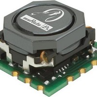
DC/DC Converters & Regulators 5Vin 0.6-3.3Vout 6A 19.8W Pos Polarity
Manufacturer
Murata Power Solutions Inc
Datasheet
1.OKL-T6-W5N-C.pdf
(18 pages)
Specifications of OKL-T/6-W5P-C
Output Power
19.8 W
Input Voltage Range
2.4 V to 5.5 V
Input Voltage (nominal)
5 V
Number Of Outputs
1
Package / Case Size
12.2 mm x 12.2 mm x7.2 mm
Output Voltage
0.6 V to 3.3 V
Product
Non-Isolated / POL
Lead Free Status / RoHS Status
Lead free / RoHS Compliant


impedances between the power supply and its load. In order to minimize
circuit errors and standardize tests between units, scope measurements
should be made using BNC connectors or the probe ground should not
exceed one half inch and soldered directly to the test circuit.
Minimum Output Loading Requirements
All models regulate within specifi cation and are stable under no load to full
load conditions. Operation under no load might however slightly increase
output ripple and noise.
Thermal Shutdown
To prevent many over temperature problems and damage, these converters
include thermal shutdown circuitry. If environmental conditions cause the
temperature of the DC/DC’s to rise above the Operating Temperature Range
up to the shutdown temperature, an on-board electronic temperature
sensor will power down the unit. When the temperature decreases below
the turn-on threshold, the converter will automatically restart. There is a
small amount of hysteresis to prevent rapid on/off cycling.
may shut down suddenly without warning. Be sure to thoroughly test your
application to avoid unplanned thermal shutdown.
Temperature Derating Curves
The graphs in the next section illustrate typical operation under a variety of
conditions. The Derating curves show the maximum continuous ambient air
temperature and decreasing maximum output current which is accept-
able under increasing forced airfl ow measured in Linear Feet per Minute
(“LFM”). Note that these are AVERAGE measurements. The converter will
accept brief increases in current or reduced airfl ow as long as the average
is not exceeded.
itself which is obviously running at higher temperature than the outside
air. Also note that very low fl ow rates (below about 25 LFM) are similar to
“natural convection”, that is, not using fan-forced airfl ow.
closed cycle wind tunnel with calibrated airflow. We use both thermo-
couples and an infrared camera system to observe thermal performance.
V
IN
In fi gure 5, the two copper strips simulate real-world printed circuit
CAUTION: If you operate too close to the thermal limits, the converter
Note that the temperatures are of the ambient airfl ow, not the converter
Murata Power Solutions makes Characterization measurements in a
OSCILLOSCOPE
C
C
L
+
+
BUS
–
–
IN
BUS
TO
= 2 x 100μF, ESR < 700mΩ @ 100kHz
= 1μH
= 1000μF, ESR < 100mΩ @ 100kHz
C
Figure 4: Measuring Input Ripple Current
BUS
L
BUS
CURRENT
PROBE
C
IN
+INPUT
-INPUT
www.murata-ps.com
altitude. Be sure to reduce the derating for higher density altitude.
Output Voltage Sequencing
The OKL modules include a sequencing feature that enables users to
implement various types of output voltage sequencing in their applications.
This is accomplished via an additional sequencing pin. When not using the
sequencing feature, either tie the sequence pin to Vin or leave it uncon-
nected.
voltage tracks this voltage until the output reaches the set-point voltage.
The fi nal value of the sequence voltage must be set higher than the set-
point voltage of the module. The output voltage follows the voltage on the
sequence pin on a one-to-one volt basis. By connecting multiple modules
together, multiple modules can track their output voltages to the voltage
applied on the sequence pin.
module. The On/Off pin of the module is left unconnected (or tied to GND
for negative logic modules or tied to Vin for positive logic modules) so that
the module is ON by default. After applying input voltage to the module,
a minimum 10msec delay is required before applying voltage on the
sequence pin. During this time, a voltage of 50mV (± 20 mV) is maintained
on the sequence pin. This delay gives the module enough time to complete
its internal powerup soft-start cycle. During the delay time, the sequence
pin should be held close to ground (nominally 50mV ± 20 mV). This is re-
quired to keep the internal opamp out of saturation thus preventing output
overshoot during the start of the sequencing ramp. By selecting resistor R1
according to the following equation
signal is at zero.
Click here to view Application Note DCAN-61
CAUTION: These graphs are all collected at slightly above Sea Level
When an analog voltage is applied to the sequence pin, the output
For proper voltage sequencing, fi rst, input voltage is applied to the
the voltage at the sequencing pin will be 50mV when the sequencing
Programmable Output 6-Amp iLGA SMT PoLs
+OUTPUT
-OUTPUT
Figure 5: Measuring Output Ripple and Noise (PARD)
09 May 2011 MDC_OKL-T/6-W5 Series.A08 Page 15 of 18
C1 = 1μF CERAMIC
C2 = 10μF CERAMIC
LOAD 2-3 INCHES (51-76mm) FROM MODULE
R1 = ———— ohms,
OKL-T/6-W5 Series
C1
Vin – 0.05
23500
COPPER STRIP
COPPER STRIP
email: sales@murata-ps.com
C2
SCOPE
R
LOAD
Related parts for OKL-T/6-W5P-C
Image
Part Number
Description
Manufacturer
Datasheet
Request
R

Part Number:
Description:
CONV DC/DC 19.8W 6A 5VIN SMD
Manufacturer:
Murata Power Solutions Inc
Datasheet:

Part Number:
Description:
CONV DC/DC 30W 6A 12VIN SMD
Manufacturer:
Murata Power Solutions Inc
Datasheet:

Part Number:
Description:
DC/DC Converters & Regulators 12Vin .59-5.5Vout 6A 30W Pos Polarity
Manufacturer:
Murata Power Solutions Inc
Datasheet:

Part Number:
Description:
CONV DC/DC 15W 12VIN 3AOUT SMD
Manufacturer:
Murata Power Solutions Inc
Datasheet:

Part Number:
Description:
CONV DC/DC 9.9W 3A 5VIN SMD
Manufacturer:
Murata Power Solutions Inc
Datasheet:

Part Number:
Description:
CONV DC/DC 15W 12VIN 3AOUT SMD
Manufacturer:
Murata Power Solutions Inc
Datasheet:
Part Number:
Description:
DC/DC Converters & Regulators 5Vin 0.6-3.63Vout 3A 9.9W Pos Polarity
Manufacturer:
Murata Power Solutions Inc
Datasheet:

Part Number:
Description:
DC-DC CONVERTER, 5.5V, 5W
Manufacturer:
Murata Power Solutions Inc
Datasheet:
Part Number:
Description:
DC-DC CONVERTER, 5.5V, 5W
Manufacturer:
Murata Power Solutions Inc
Datasheet:

Part Number:
Description:
Transformers 5Vin 5Vout 200mA 4000Vdc 1:1.33 turn
Manufacturer:
Murata Power Solutions Inc
Datasheet:

Part Number:
Description:
POWER SUPPLY
Manufacturer:
Murata Power Solutions Inc
Datasheet:

Part Number:
Description:
DPM LED MINI 2VDC 3.5DIG LP RED
Manufacturer:
Murata Power Solutions Inc
Datasheet:

Part Number:
Description:
CONV DC/DC 1W 5VIN 5VOUT SIP SGL
Manufacturer:
Murata Power Solutions Inc
Datasheet:

Part Number:
Description:
CONV DC/DC 1W 5VIN 3.3V SIP SGL
Manufacturer:
Murata Power Solutions Inc
Datasheet: