OKL-T/1-W12N-C Murata Power Solutions Inc, OKL-T/1-W12N-C Datasheet
OKL-T/1-W12N-C
Specifications of OKL-T/1-W12N-C
Available stocks


Related parts for OKL-T/1-W12N-C


OKL-T/1-W12N-C Summary of contents
Page 1
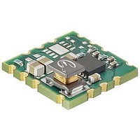
... For full details go to www.murata-ps.com/rohs PRODUCT OVERVIEW The OKL-T/1-W12 series are non-isolated Point- of-Load (PoL) DC/DC power converters for embed- ded applications. Featuring inspectable Land Grid Array (iLGA) format, the OKL-T/1-W12 measures only 0.488 x 0.488 x 0.18 inches max. (12 ...
Page 2
... Input Voltage Range 2.9–14Vdc Maximum Rated Output Current in Amps OKL-T/1-W12P-C OKL-T/1-W12N-C The manufacturing date code is four characters: First character – Last digit of manufacturing year, example 2009 Second character – Month code (1 through 9 and O through D) Third character – Day code (1 through 10=O and 11 through through Z) Fourth character – ...
Page 3
... The On/Off Control Input should use either a switch or an open collector/open drain transistor referenced to -Input Common. A logic gate may also be used by applying appropriate external voltages which do not exceed +Vin. Short circuit shutdown begins when the output voltage degrades approximately 2% from the selected setting. email: sales@murata-ps.com 09 May 2011 MDC_OKL-T/1-W12 Series.A04 Page ...
Page 4
... This short current pulse prevents overheating and damaging the converter. Once the fault is removed, the converter immediately recovers normal operation. www.murata-ps.com 09 May 2011 OKL-T/1-W12 Series email: sales@murata-ps.com MDC_OKL-T/1-W12 Series.A04 Page ...
Page 5
... Dimensions are in inches (mm shown for ref. only). Third Angle Projection Tolerances (unless otherwise specified): .XX ± 0.02 (0.5) .XXX ± 0.010 (0.25) Angles ± 1˚ Components are shown for reference only. email: sales@murata-ps.com 09 May 2011 MDC_OKL-T/1-W12 Series.A04 Page Function Vin Ground Vout1 Trim1 Ground Ground ...
Page 6
... Vin Gnd On/Off Gnd Gnd NC Trim1 4.57 0.180 0.090 C L www.murata-ps.com OKL-T/1-W12 Series Programmable Output 1-Amp iLGA SMT PoLs 0.070-0.080 [1.78-2.03mm] x 0.160-0.170 [4.06-4.32mm] 3 PLACES 3 3.43 0.135 4.57 11 0.180 6 0.040-0.050 [1.02-1.27mm] SQUARE PAD (9 PLS) 2.29 email: sales@murata-ps.com 09 May 2011 MDC_OKL-T/1-W12 Series.A04 Page ...
Page 7
... FEED (UNWIND) DIRECTION 5.00 0.197 4.00 0.157 REF 0.77 2.00 0.030 0.079 Contents: 800 units per reel 16.00 0.63 PITCH TOP COVER TAPE www.murata-ps.com OKL-T/1-W12 Series 1.50 0.059 TYP 1.75 0.069 13.41 0.528 5.00 0.197 email: sales@murata-ps.com 09 May 2011 MDC_OKL-T/1-W12 Series.A04 Page ...
Page 8
... Vout = 5V, airfl from pad 10 to pad 1) 65 LFM Ambient Temperature (ºC) Maximum Current Temperature Derating at Sea Level (Vin = 6.5V to 16V, airfl from pad 10 to pad 1) 65 LFM Ambient Temperature (ºC) ScopeBW=100MHz) email: sales@murata-ps.com 09 May 2011 MDC_OKL-T/1-W12 Series.A04 Page ...
Page 9
... Step Load Transient Response (Vin=4.5V, Vout=3.3V, Cload=0, Iout=1A to 0.5A, Ta=+25°C.) Trace 2=Vout, 100 mV/div. Trace 4=Iout, 0.5A/div. Step Load Transient Response (Vin=12V, Vout=3.3V, Cload=0, Iout=1A to 0.5A, Ta=+25°C.) Trace 2=Vout, 100 mV/div. Trace 4=Iout, 0.5A/div. www.murata-ps.com 09 May 2011 OKL-T/1-W12 Series email: sales@murata-ps.com MDC_OKL-T/1-W12 Series.A04 Page ...
Page 10
... Output Ripple and Noise (Vin=12V, Vout=2.5V, Iout=1A, Cload=0, Ta=+25°C., www.murata-ps.com OKL-T/1-W12 Series Maximum Current Temperature Derating at Sea Level (Vin = 4V, Vout = 2.5V) 65 LFM Ambient Temperature (ºC) ScopeBW=100MHz) email: sales@murata-ps.com 09 May 2011 MDC_OKL-T/1-W12 Series.A04 Page ...
Page 11
... Step Load Transient Response (Vin=3.5V, Vout=2.5V, Cload=0, Iout=1A to 0.5A, Ta=+25°C.) Trace 2=Vout, 100 mV/div. Trace 4=Iout, 0.5A/div. Step Load Transient Response (Vin=12V, Vout=2.5V, Cload=0, Iout=1A to 0.5A, Ta=+25°C.) Trace 2=Vout, 100 mV/div. Trace 4=Iout, 0.5A/div. www.murata-ps.com 09 May 2011 OKL-T/1-W12 Series email: sales@murata-ps.com MDC_OKL-T/1-W12 Series.A04 Page ...
Page 12
... Effi ciency vs. Line Voltage and Load Current @Ta = +25 °C (Vout = 1.5V 2. 12V 14V IN 0 0.1 0.2 0.3 0.4 0.5 0.6 Load C urre nt (Amps) www.murata-ps.com OKL-T/1-W12 Series Maximum Current Temperature Derating at Sea Level (Vin = 4V, Vout = 1.8V) 65 LFM Ambient Temperature (ºC) 0.7 0.8 0.9 1 email: sales@murata-ps.com 09 May 2011 MDC_OKL-T/1-W12 Series.A04 Page ...
Page 13
... Output Ripple and Noise (Vin=14V, Vout=0.9V, Iout=1A, Cload=0, Ta=+25°C., ScopeBW=100MHz) Step Load Transient Response (Vin=2.6V, Vout=0.9V, Cload=0, Iout=1A to 0.5A, Ta=+25°C.) Trace 2=Vout, 100 mV/div. Trace 4=Iout, 0.5A/div. www.murata-ps.com OKL-T/1-W12 Series Ta=+25°C., ScopeBW=100MHz) email: sales@murata-ps.com 09 May 2011 MDC_OKL-T/1-W12 Series.A04 Page ...
Page 14
... Step Load Transient Response (Vin=12V, Vout=0.9V, Cload=0, Iout=1A to 0.5A, Ta=+25°C.) Trace 2=Vout, 100 mV/div. Trace 4=Iout, 0.5A/div. Step Load Transient Response (Vin=14V, Vout=0.9V, Cload=0, Iout=1A to 0.5A, Ta=+25°C.) Trace 2=Vout, 100 mV/div. Trace 4=Iout, 0.5A/div. www.murata-ps.com 09 May 2011 OKL-T/1-W12 Series email: sales@murata-ps.com MDC_OKL-T/1-W12 Series.A04 Page ...
Page 15
... Use only as much capacitance as required to achieve your ripple and noise objectives. Excessive capacitance can make step load recovery sluggish or possibly introduce instability. Do not exceed the maximum rated output capacitance listed in the specifi cations. www.murata-ps.com OKL-T/1-W12 Series email: sales@murata-ps.com 09 May 2011 MDC_OKL-T/1-W12 Series.A04 Page ...
Page 16
... The system will automatically restore operation as soon as the short circuit condition is removed. www.murata-ps.com OKL-T/1-W12 Series COPPER STRIP SCOPE C1 C2 COPPER STRIP C1 = 1μF CERAMIC C2 = 10μF CERAMIC LOAD 2-3 INCHES (51-76mm) FROM MODULE email: sales@murata-ps.com 09 May 2011 MDC_OKL-T/1-W12 Series.A04 Page LOAD ...
Page 17
... Remote On/Off Control The OKL Series power modules can be specifi ed with either a positive or nega- tive logic polarity. See Figures 7 and 8 for On/Off circuit control. In the positive logic on/off option the unit turns on during a logic high on the On/Off pin and turns off during a logic low negative logic on/off option, the unit turns off during logic high and on during logic low ...
Page 18
... The descriptions contained herein do not imply the granting of licenses to make, use, or sell equipment constructed in accordance therewith. Specifi cations are subject to change without notice. www.murata-ps.com/locations OKL-T/1-W12 Series © 2011 Murata Power Solutions, Inc. email: sales@murata-ps.com 09 May 2011 MDC_OKL-T/1-W12 Series.A04 Page ...