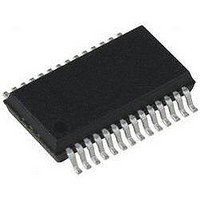
PIC18LF24K22-I/SS Microchip Technology, PIC18LF24K22-I/SS Datasheet - Page 48

PIC18LF24K22-I/SS
Manufacturer Part Number
PIC18LF24K22-I/SS
Description
IC PIC MCU 16KB FLASH 28SSOP
Manufacturer
Microchip Technology
Series
PIC® XLP™ 18Fr
Specifications of PIC18LF24K22-I/SS
Core Size
8-Bit
Program Memory Size
16KB (8K x 16)
Core Processor
PIC
Speed
64MHz
Connectivity
I²C, SPI, UART/USART
Peripherals
Brown-out Detect/Reset, HLVD, POR, PWM, WDT
Number Of I /o
24
Program Memory Type
FLASH
Eeprom Size
256 x 8
Ram Size
768 x 8
Voltage - Supply (vcc/vdd)
1.8 V ~ 3.6 V
Data Converters
A/D 19x10b
Oscillator Type
Internal
Operating Temperature
-40°C ~ 85°C
Package / Case
28-SSOP (0.200", 5.30mm Width)
Controller Family/series
PIC18
No. Of I/o's
25
Eeprom Memory Size
256Byte
Ram Memory Size
768Byte
Cpu Speed
64MHz
No. Of Timers
7
Lead Free Status / RoHS Status
Lead free / RoHS Compliant
- Current page: 48 of 496
- Download datasheet (5Mb)
PIC18(L)F2X/4XK22
3.1.3
The power-managed mode that is invoked with the
SLEEP instruction is determined by the value of the
IDLEN bit at the time the instruction is executed. If
IDLEN = 0, when SLEEP is executed, the device enters
the sleep mode and all clocks stop and minimum power
is consumed. If IDLEN = 1, when SLEEP is executed,
the device enters the IDLE mode and the system clock
continues to supply a clock to the peripherals but is
disconnected from the CPU.
3.2
In the Run modes, clocks to both the core and
peripherals are active. The difference between these
modes is the clock source.
3.2.1
The PRI_RUN mode is the normal, full-power
execution mode of the microcontroller. This is also the
default mode upon a device Reset, unless Two-Speed
Start-up is enabled (see
Clock Start-up Mode”
device is operated off the oscillator defined by the
FOSC<3:0> bits of the CONFIG1H Configuration
register.
3.2.2
In SEC_RUN mode, the CPU and peripherals are
clocked from the secondary external oscillator. This
gives users the option of lower power consumption
while still using a high accuracy clock source.
SEC_RUN mode is entered by setting the SCS<1:0>
bits to ‘01’. When SEC_RUN mode is active, all of the
following are true:
• The device clock source is switched to the SOSC
• The primary oscillator is shut down
• The SOSCRUN bit (OSCCON2<6>) is set
• The OSTS bit (OSCCON2<3>) is cleared
On transitions from SEC_RUN mode to PRI_RUN
mode, the peripherals and CPU continue to be clocked
from the SOSC oscillator, while the primary clock is
started. When the primary clock becomes ready, a
clock switch back to the primary clock occurs (see
DS41412D-page 48
oscillator (see
Note:
Run Modes
MULTIPLE FUNCTIONS OF THE
SLEEP COMMAND
PRI_RUN MODE
SEC_RUN MODE
The secondary external oscillator should
already be running prior to entering
SEC_RUN mode. If the SOSCGO bit or
any of the TxSOSCEN bits are not set
when the SCS<1:0> bits are set to ‘01’,
entry to SEC_RUN mode will not occur
until SOSCGO bit is set and secondary
external oscillator is ready.
Figure
3-1)
for details). In this mode, the
Section 2.10 “Two-Speed
Preliminary
Figure
SOSCRUN bit is cleared, the OSTS bit is set and the
primary clock is providing the clock. The IDLEN and
SCS bits are not affected by the wake-up and the
SOSC oscillator continues to run.
3.2.3
In RC_RUN mode, the CPU and peripherals are
clocked from the internal oscillator block using the
INTOSC multiplexer. In this mode, the primary clock is
shut down. When using the LFINTOSC source, this
mode provides the best power conservation of all the
Run modes, while still executing code. It works well for
user applications which are not highly timing-sensitive
or do not require high-speed clocks at all times. If the
primary clock source is the internal oscillator block –
either
HFINTOSC) – there are no distinguishable differences
between the PRI_RUN and RC_RUN modes during
execution. Entering or exiting RC_RUN mode,
however, causes a clock switch delay. Therefore, if the
primary clock source is the internal oscillator block,
using RC_RUN mode is not recommended.
This mode is entered by setting the SCS1 bit to ‘1’. To
maintain software compatibility with future devices, it is
recommended that the SCS0 bit also be cleared, even
though the bit is ignored. When the clock source is
switched to the INTOSC multiplexer (see
the primary oscillator is shut down and the OSTS bit is
cleared. The IRCF<2:0> bits (OSCCON<6:4>) may be
modified at any time to immediately change the clock
speed.
When the IRCF bits and the INTSRC bit are all clear,
the INTOSC output (HFINTOSC/MFINTOSC) is not
enabled and the HFIOFS and MFIOFS bits will remain
clear. There will be no indication of the current clock
source. The LFINTOSC source is providing the device
clocks.
If the IRCF bits are changed from all clear (thus,
enabling the INTOSC output) or if INTSRC or MFIOSEL
is set, then the HFIOFS or MFIOFS bit is set after the
INTOSC output becomes stable. For details, see
Table
Clocks to the device continue while the INTOSC source
stabilizes after an interval of T
If the IRCF bits were previously at a non-zero value, or
if INTSRC was set before setting SCS1 and the
INTOSC source was already stable, then the HFIOFS
or MFIOFS bit will remain set.
3-2.
3-2). When the clock switch is complete, the
LFINTOSC
RC_RUN MODE
or
2010 Microchip Technology Inc.
INTOSC
IOBST
.
(MFINTOSC
Figure
3-1),
or
Related parts for PIC18LF24K22-I/SS
Image
Part Number
Description
Manufacturer
Datasheet
Request
R

Part Number:
Description:
Manufacturer:
Microchip Technology Inc.
Datasheet:

Part Number:
Description:
Manufacturer:
Microchip Technology Inc.
Datasheet:

Part Number:
Description:
Manufacturer:
Microchip Technology Inc.
Datasheet:

Part Number:
Description:
Manufacturer:
Microchip Technology Inc.
Datasheet:

Part Number:
Description:
Manufacturer:
Microchip Technology Inc.
Datasheet:

Part Number:
Description:
Manufacturer:
Microchip Technology Inc.
Datasheet:

Part Number:
Description:
Manufacturer:
Microchip Technology Inc.
Datasheet:

Part Number:
Description:
Manufacturer:
Microchip Technology Inc.
Datasheet:


