PIC18LF24K22-I/SS Microchip Technology, PIC18LF24K22-I/SS Datasheet - Page 186
PIC18LF24K22-I/SS
Manufacturer Part Number
PIC18LF24K22-I/SS
Description
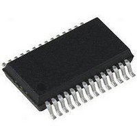
IC PIC MCU 16KB FLASH 28SSOP
Manufacturer
Microchip Technology
Series
PIC® XLP™ 18Fr
Specifications of PIC18LF24K22-I/SS
Core Size
8-Bit
Program Memory Size
16KB (8K x 16)
Core Processor
PIC
Speed
64MHz
Connectivity
I²C, SPI, UART/USART
Peripherals
Brown-out Detect/Reset, HLVD, POR, PWM, WDT
Number Of I /o
24
Program Memory Type
FLASH
Eeprom Size
256 x 8
Ram Size
768 x 8
Voltage - Supply (vcc/vdd)
1.8 V ~ 3.6 V
Data Converters
A/D 19x10b
Oscillator Type
Internal
Operating Temperature
-40°C ~ 85°C
Package / Case
28-SSOP (0.200", 5.30mm Width)
Controller Family/series
PIC18
No. Of I/o's
25
Eeprom Memory Size
256Byte
Ram Memory Size
768Byte
Cpu Speed
64MHz
No. Of Timers
7
Lead Free Status / RoHS Status
Lead free / RoHS Compliant


PIC18(L)F2X/4XK22
14.3.6
The resolution determines the number of available duty
cycles for a given period. For example, a 10-bit resolution
will result in 1024 discrete duty cycles, whereas an 8-bit
resolution will result in 256 discrete duty cycles.
The maximum PWM resolution is 10 bits when PRx is
255. The resolution is a function of the PRx register
value as shown by
TABLE 14-7:
TABLE 14-8:
TABLE 14-9:
14.3.7
In Sleep mode, the TMRx register will not increment
and the state of the module will not change. If the CCPx
pin is driving a value, it will continue to drive that value.
When the device wakes up, TMRx will continue from its
previous state.
14.3.8
The PWM frequency is derived from the system clock
frequency. Any changes in the system clock frequency
will result in changes to the PWM frequency. See
Section 2.0 “Oscillator Module (With Fail-Safe
Clock Monitor)”
DS41412D-page 186
Timer Prescale (1, 4, 16)
PRx Value
Maximum Resolution (bits)
Timer Prescale (1, 4, 16)
PRx Value
Maximum Resolution (bits)
Timer Prescale (1, 4, 16)
PRx Value
Maximum Resolution (bits)
PWM Frequency
PWM Frequency
PWM Frequency
PWM RESOLUTION
OPERATION IN SLEEP MODE
CHANGES IN SYSTEM CLOCK
FREQUENCY
for additional details.
EXAMPLE PWM FREQUENCIES AND RESOLUTIONS (F
EXAMPLE PWM FREQUENCIES AND RESOLUTIONS (F
EXAMPLE PWM FREQUENCIES AND RESOLUTIONS (F
Equation
14-4.
1.95 kHz
1.22 kHz
1.22 kHz
0xFF
0xFF
0x65
16
10
16
10
16
8
7.81 kHz
4.88 kHz
4.90 kHz
0xFF
0xFF
Preliminary
0x65
10
10
4
4
4
8
31.25 kHz
19.53 kHz
19.61 kHz
EQUATION 14-4:
14.3.9
Any Reset will force all ports to Input mode and the
CCP registers to their Reset states.
0xFF
0xFF
Note:
0x65
10
10
1
1
1
8
Resolution
If the pulse width value is greater than the
period the assigned PWM pin(s) will
remain unchanged.
EFFECTS OF RESET
78.12 kHz
76.92 kHz
125 kHz
0x3F
0x3F
0x19
1
8
1
8
1
6
OSC
OSC
OSC
=
PWM RESOLUTION
log
----------------------------------------- - bits
2010 Microchip Technology Inc.
= 32 MHz)
= 20 MHz)
= 8 MHz)
4 PRx
153.85 kHz
log
156.3 kHz
250 kHz
0x0C
0x1F
0x1F
2
1
7
1
7
1
5
+
1
333.3 kHz
208.3 kHz
200.0 kHz
0x17
0x17
0x09
6.6
6.6
1
1
1
5
Related parts for PIC18LF24K22-I/SS
Image
Part Number
Description
Manufacturer
Datasheet
Request
R

Part Number:
Description:
Manufacturer:
Microchip Technology Inc.
Datasheet:
Part Number:
Description:
Manufacturer:
Microchip Technology Inc.
Datasheet:
Part Number:
Description:
Manufacturer:
Microchip Technology Inc.
Datasheet:
Part Number:
Description:
Manufacturer:
Microchip Technology Inc.
Datasheet:
Part Number:
Description:
Manufacturer:
Microchip Technology Inc.
Datasheet:
Part Number:
Description:
Manufacturer:
Microchip Technology Inc.
Datasheet:
Part Number:
Description:
Manufacturer:
Microchip Technology Inc.
Datasheet:
Part Number:
Description:
Manufacturer:
Microchip Technology Inc.
Datasheet: