PIC18LF24K22-I/SS Microchip Technology, PIC18LF24K22-I/SS Datasheet - Page 398
PIC18LF24K22-I/SS
Manufacturer Part Number
PIC18LF24K22-I/SS
Description
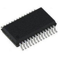
IC PIC MCU 16KB FLASH 28SSOP
Manufacturer
Microchip Technology
Series
PIC® XLP™ 18Fr
Specifications of PIC18LF24K22-I/SS
Core Size
8-Bit
Program Memory Size
16KB (8K x 16)
Core Processor
PIC
Speed
64MHz
Connectivity
I²C, SPI, UART/USART
Peripherals
Brown-out Detect/Reset, HLVD, POR, PWM, WDT
Number Of I /o
24
Program Memory Type
FLASH
Eeprom Size
256 x 8
Ram Size
768 x 8
Voltage - Supply (vcc/vdd)
1.8 V ~ 3.6 V
Data Converters
A/D 19x10b
Oscillator Type
Internal
Operating Temperature
-40°C ~ 85°C
Package / Case
28-SSOP (0.200", 5.30mm Width)
Controller Family/series
PIC18
No. Of I/o's
25
Eeprom Memory Size
256Byte
Ram Memory Size
768Byte
Cpu Speed
64MHz
No. Of Timers
7
Lead Free Status / RoHS Status
Lead free / RoHS Compliant


PIC18(L)F2X/4XK22
RETFIE
Syntax:
Operands:
Operation:
Status Affected:
Encoding:
Description:
Words:
Cycles:
Example:
DS41412D-page 398
Q Cycle Activity:
After Interrupt
operation
Decode
PC
W
BSR
Status
GIE/GIEH, PEIE/GIEL
Q1
No
operation
operation
Return from Interrupt
RETFIE {s}
s [0,1]
(TOS) PC,
1 GIE/GIEH or PEIE/GIEL,
if s = 1
(WS) W,
(STATUSS) Status,
(BSRS) BSR,
PCLATU, PCLATH are unchanged.
GIE/GIEH, PEIE/GIEL.
Return from interrupt. Stack is popped
and Top-of-Stack (TOS) is loaded into
the PC. Interrupts are enabled by
setting either the high or low priority
global interrupt enable bit. If ‘s’ = 1, the
contents of the shadow registers, WS,
STATUSS and BSRS, are loaded into
their corresponding registers, W,
Status and BSR. If ‘s’ = 0, no update of
these registers occurs (default).
1
2
RETFIE
0000
Q2
No
No
1
0000
operation
operation
=
=
=
=
=
Q3
No
No
TOS
WS
BSRS
STATUSS
1
0001
Set GIEH or
from stack
operation
POP PC
GIEL
Q4
No
000s
Preliminary
RETLW
Syntax:
Operands:
Operation:
Status Affected:
Encoding:
Description:
Words:
Cycles:
Example:
TABLE
Q Cycle Activity:
:
:
:
CALL TABLE ; W contains table
ADDWF PCL
RETLW k0
RETLW k1
RETLW kn
Before Instruction
After Instruction
operation
Decode
W
W
Q1
No
; offset value
; W now has
; table value
; W = offset
; Begin table
;
; End of table
=
=
operation
Return literal to W
RETLW k
0 k 255
k W,
(TOS) PC,
PCLATU, PCLATH are unchanged
None
W is loaded with the eight-bit literal ‘k’.
The program counter is loaded from the
top of the stack (the return address).
The high address latch (PCLATH)
remains unchanged.
1
2
literal ‘k’
Read
0000
Q2
No
07h
value of kn
2010 Microchip Technology Inc.
1100
operation
Process
Data
Q3
No
kkkk
from stack,
Write to W
operation
POP PC
Q4
No
kkkk
Related parts for PIC18LF24K22-I/SS
Image
Part Number
Description
Manufacturer
Datasheet
Request
R

Part Number:
Description:
Manufacturer:
Microchip Technology Inc.
Datasheet:
Part Number:
Description:
Manufacturer:
Microchip Technology Inc.
Datasheet:
Part Number:
Description:
Manufacturer:
Microchip Technology Inc.
Datasheet:
Part Number:
Description:
Manufacturer:
Microchip Technology Inc.
Datasheet:
Part Number:
Description:
Manufacturer:
Microchip Technology Inc.
Datasheet:
Part Number:
Description:
Manufacturer:
Microchip Technology Inc.
Datasheet:
Part Number:
Description:
Manufacturer:
Microchip Technology Inc.
Datasheet:
Part Number:
Description:
Manufacturer:
Microchip Technology Inc.
Datasheet: