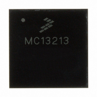
MC13213 Freescale Semiconductor, MC13213 Datasheet - Page 49

MC13213
Manufacturer Part Number
MC13213
Description
IC TXRX RF 2.4GHZ FLSH 60K 71LGA
Manufacturer
Freescale Semiconductor
Series
MC1321xr
Datasheet
1.1321XCSK-BDM.pdf
(70 pages)
Specifications of MC13213
Frequency
2.4GHz
Data Rate - Maximum
250kbps
Modulation Or Protocol
802.15.4 Zigbee
Applications
General Purpose
Power - Output
3dBm
Sensitivity
-92dBm
Voltage - Supply
1.8 V ~ 3.6 V
Current - Receiving
42mA
Current - Transmitting
35mA
Data Interface
PCB, Surface Mount
Memory Size
60kB Flash, 4kB RAM
Antenna Connector
PCB, Surface Mount
Operating Temperature
-40°C ~ 85°C
Package / Case
71-LGA
Number Of Receivers
1
Number Of Transmitters
1
Wireless Frequency
2.4 GHz to 2.48 GHz
Interface Type
SPI
Output Power
0 dBm to 2 dBm
Operating Supply Voltage
2 V to 3.4 V
Maximum Operating Temperature
+ 85 C
Mounting Style
SMD/SMT
Maximum Supply Current
42 mA
Minimum Operating Temperature
- 40 C
Protocol Supported
802.15.4
Lead Free Status / RoHS Status
Lead free / RoHS Compliant
Available stocks
Company
Part Number
Manufacturer
Quantity
Price
Company:
Part Number:
MC13213
Manufacturer:
FREESCALE Semiconductor
Quantity:
337
Part Number:
MC13213
Manufacturer:
FREESCALE
Quantity:
20 000
Company:
Part Number:
MC13213R2
Manufacturer:
BROADCOM
Quantity:
1
Part Number:
MC13213R2
Manufacturer:
FREESCALE
Quantity:
20 000
Freescale Semiconductor
1
2
3
Power Spectral Density (-40 to +85 °C) Absolute limit
Power Spectral Density (-40 to +85 °C) Relative limit
Nominal Output Power
Maximum Output Power
Error Vector Magnitude
Ouput Power Control Range
Over the Air Data Rate
2nd Harmonic
3rd Harmonic
Frequency Error Tolerance
Symbol Rate Error Tolerance
U4
MC1321x
RFIN_M
CT_Bias
RFIN_P
SPI Register 12 is default value of 0x00BC which sets output power to nominal (-1 dBm typical).
SPI Register 12 programmed to 0xFF which sets output power to maximum.
Measured with output power set to nominal (0 dBm) and temperature @ 25 °C
PAO_M
PAO_P
GPIO1
44
39
38
36
35
34
3
3
1
2
(V
(V
Characteristic
BATT
BATT
Characteristic
, V
, V
Table 10. Transmitter AC Electrical Characteristics
DDINT
DDINT
Table 9. Receiver AC Electrical Characteristics
L10
4.7nH
L11
4.7nH
L13
3.3nH
L14
3.3nH
Figure 26. RF Parametric Evaluation Circuit
MC13211/212/213 Technical Data, Rev. 1.8
= 2.7 V, T
= 2.7 V, T
C17
1.0pF
C18
1.8pF
VDDA
A
A
C12
10pF
= 25 °C, f
= 25 °C, f
3
2
4
3
2
4
Z4
LDB212G4005C-001
Z5
LDB212G4005C-001
1
5
6
1
5
6
ref
ref
= 16 MHz, unless otherwise noted.)
= 16 MHz, unless otherwise noted.)
C13
10pF
C14
10pF
Symbol
EVM
P
out
3
1
2
IC2
µPG2012TK-E2
OUT2
OUT1
GND
VCONT
Symbol
VDD
IN
6
5
4
Min
-4
-
-
-
-
-
-
-
C16
10pF
L12
2.2nH
Min
-
-
Typ
250
-47
-48
-70
47
18
30
0
3
C15
1.8pF
Typ
-
-
Max
35
2
-
-
-
-
-
-
Max
200
2
3
4
5
80
J3
SMA_edge_Recep
dBm
dBm
dBm
kbps
Unit
dBc
dBc
Unit
ppm
dB
kHz
%
49


